EasyManua.ls Logo

Haier 1U09AP2VHA User Manual

Haier 1U09AP2VHA
186 pages
To Next Page IconTo Next Page
Page #1 background imageLoading...
Page #1 background image
Ductless Split Heat Pump
Service Manual
Design may vary by model number.
Please read this manual before using the heat pump.
Keep this user manual for future reference.
PAGE 1
Safety Precautions/Introduction .................................................................................................3
Outdoor Unit Controls and Components ..................................................................................... 7
Indoor Unit Controls and Components ......................................................................................15
Sequence Of Operation ............................................................................................................. 21
Error Codes and Problem Solving ..............................................................................................29
Reference Information ..............................................................................................................43
Table of Contents
Indoor
AW09ES2VHB
AW12ES2VHB
AW15ES2VHB
AW18ES2VHB
AW24ES2VHB
Outdoor
1U09AP2VHA
1U12AP2VHA
1U15AP2VHA
1U18AP2VHA
1U24AP2VHA

Table of Contents

Other manuals for Haier 1U09AP2VHA

Question and Answer IconNeed help?

Do you have a question about the Haier 1U09AP2VHA and is the answer not in the manual?

Haier 1U09AP2VHA Specifications

General IconGeneral
Cooling Capacity9000 BTU/h
Energy Efficiency Ratio (EER)3.21
RefrigerantR410A
Coefficient of Performance (COP)3.61
Indoor Unit Weight9 kg
TypeSplit Type
Operating Temperature Range (Heating)-7°C to 24°C
Power Supply220-240V/50Hz/1Ph

Summary

Safety and System Introduction

Safety Precautions

Details warnings and cautions for safe installation and operation.

System Overview and Theory

Explains system features, operational theory, and specifications.

Outdoor Unit Components and Controls

Outdoor Unit Identification and Boards

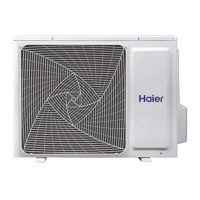
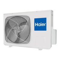
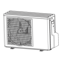
Identifies outdoor unit parts and details control board functions.

Outdoor Unit Electrical Components

Covers terminal block, compressor, fan motor, and reactor.

Outdoor Unit Sensors and Refrigerant Control

Details temperature sensors, 4-way valve, EEV, accumulator, and filters.

Outdoor Unit Auxiliary Features and Settings

Details Base Pan Heater and DIP Switch settings.

Indoor Unit Components and Controls

Indoor Unit Identification and Overview

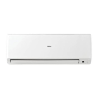
Identifies indoor unit parts and describes system features.

Indoor Control Board and Wiring

Details the indoor unit's main control board and connectors.

Indoor Unit Sensors, Display, and Motors

Explains sensors, display, motors, and settings.

Indoor Unit Configuration Settings

Outlines DIP switch settings for unit configuration.

System Operation Modes

Cool Mode Operation

Details power supply, cooling mode entry, and operation.

Heat Mode and Cold Air Proof

Explains heating mode entry, operation, and cold air prevention.

Dry Mode Operation

Describes the purpose and operation of the dry mode.

Defrost and Protection Functions

Defrost Operation

Details defrosting program entry and exit conditions.

System Protection Functions

Explains system protections like overheat and anti-freeze.

Troubleshooting and Error Codes

Indoor Unit Error Codes

Lists indoor display error codes and fan motor malfunction.

Outdoor Unit Error Codes

Lists outdoor display codes for fan, IPM, and compressor faults.

System Communication and Power Faults

Covers communication errors and power supply issues.

Protection Faults and Overloads

Details overheat, synchronism, and overload protection errors.

Component Testing and Troubleshooting

Provides steps to test components and general tips.

Reference Information

Wiring Diagrams and Schematics

Provides schematics for control boards.

Sensor Resistance Data Tables

Lists resistance values for various sensors.

Related product manuals