Installations
Domestic air conditioner
1.Ifthesupplycordisdamaged,itmustbereplacedbythemanufacturerorits
service agent or a similar quali
ed person. The type of connecting wire is
H05RN-F
or H07RN-F.
2. If the fuse on PC board is broken please change it with the
type of
T. 3.15A/250V.
3.Thewiringmethodshouldbeinlinewiththelocalwiringstandard.
4.Afterinstallation,thepowerplugshouldbeeasilyreached.
5. A breaker should be incorporated into
xed wiring. The breaker should be
all-pole
switch and the distance
betweenitstwocontactsshouldbenotless
than 3mm.
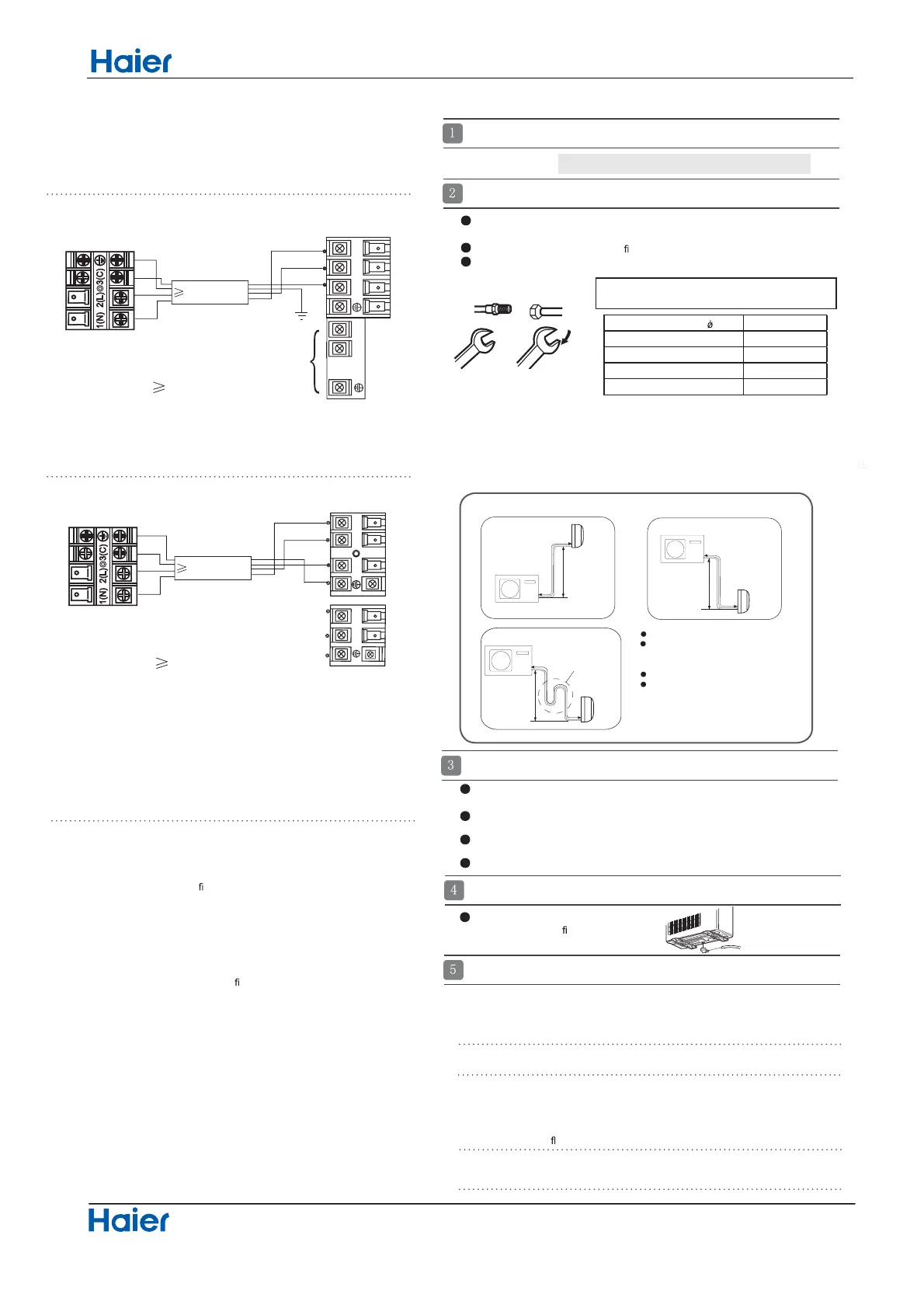
Outdoor unit
Indoor unit
A
B
Outdoor unit
Indoor unit
A
B
A
B
Outdoor unit
Indoor unit
Oil trap
Outdoor unit
Install according to Drawing for the installation of indoor and
outdoor units
To bend a pipe, give the roundness as large as possible not to crush the pipe ,
and the bending radius should be 30 to 40
mm or longer.
Connecting the pipe of gas side
rst makes working easier.
TheconnectionpipeisspecializedforR410A.
Use the same method on indoor unit. Loosen the screws on
terminal block and
insert the plugs fully into terminal block, then tighten the screws.
Insert the cable according to terminal number in the same manner as the indoor
unit.
If wiring is not correct, proper operation can not be carried out and controller
may be damaged.
Fix the cable with a clamp.
Installation of Outdoor Unit
Half union
Flare nut
Torque wrench
CAUTION
Becarefulthatmatters,suchaswastesofsands,etc.shallnotenterthepipe.
The standard pipe length is 5m. If it is over 5m, the function of the unit will be
affected. If the pipe has to be lengthened, the refrigerant should be charge
d,
accordingto20g/m.Butthechargeofrefrigerantmust
be conducted by profes-
sional air conditioner engineer. Before adding additional refrigerant, perform air
purging from the refrigerant pipes and indoor unit using a vacuum pump,then
Spanner
Forced fastening without careful centering may
damage the threads and cause a leakage of gas.
Pipe Diameter( )Fasteningtorque
Liquid side6.35mm(1/4") 18N.m
Liquid/Gas side9.52mm(3/8") 42 N.m
Gas side 12.7mm(1/2") 55N.m
Gas side 15.88mm(5/8") 60 N.m
Max.Elevation:
In case the elevation A is more
than 3m, oil trap shoud be
installed every 3~5m.
Max. Length:
IncasethepipelengthBis
more than 5m, the refrigerant
should be charged, according
to 20 g/m.
Connection of pipes
charge additional refrigerant.
Connection
If the drain-elbow is used,
please attach it as gure. (Note:
Only for heat pump unit.)
Detach the service port’s cap of
1.
3-wayvalve,thevalverod’scapfor2-wayvalve
and3-way’s,connecttheserviceportintothe
projection of charge hose (Iow)
for gaugemanifold.
Then connect the projection of charge hose (center) for gau-
gemanifold into vacuum pump.
Open the handle at Iow in
2.
gaugemanifold, operate vacuum pump. If the scale-
moves of gause (Iow) reach vacuum condition in a moment, check
1. again.
Vacuumi
zeforover15min.Andcheckthelevelgaugewhichshouldread-0.1MPa
3.
(76 cm Hg) at Iow
pressure side. After the
completion of vacuumizing, close the
handle ‘Lo’ in gaugemanifold and stop the operation of the vacuum pump. Check
condition of the scale and hold it for 1-2min. If the scale-moves back in spite of
tightening, make
aring work again, the return to the beginning of 3 .
Attaching Drain-Elbow
Purging Method:To use vacuum pump
Openthevalverodforthe2-wayvalvetoanangle of4.
anticlockwise 90 degrees.
After 6 seconds, close the
2-way valve and make the
inspection of gas leakage.
Amax=7m
Bmax=10m
Indoor unit
4G0.75mm
2
)
C
(3
)
N
(1
)L(
2
)
C
(3
)
N
(1)
L(
2
POWER
Power cable: 3G1.5mm
2
Outdoor unit
1U09BS3ERA
1U12BS3ERA
1U18FS3ERA
Indoor unit
4G0.75mm
2
POWER
Power cable: 3G2.5mm
2
N
(
1
3
)
)
C(L
(
2
)
{
L
N
Outdoor unit
33

 Loading...