Installation Manual For Wire Controller
7
There are three methods to connection wire controller and the indoor units:
A.One wired controller can control max. up to 16 sets of indoor units, and 3 pieces of polar wire must connect the wire
controller and the master unit (the indoor unit connected with wire controller directly), the others connect with the master
unit through 2 pieces of polar wire
B. One wire controller controls one indoor unit, and the indoor u
nit connects with the wire controller through 3 pieces of
polar wire.
C. Two wired controllers control one indoor unit. The wire controller connected with indoor unit is called master one, the
other is called slave one. Master wire controller and indoor unit; master and slave wire controllers are all connected
through 3 pieces of polar wire.
6. Communication wiring:
The wire
controller is equipped with special communication wiring in the accessories. 3-core terminal (1-white 2-yellow 3-
red) is connected with the terminal A, B, C of wire controller respectively.
The communication wiring is 5 meter long; if the actual length is more than it, please distribute wiring according to below
table:
Communication wiring length(m) Dimensions of wiring
< 100 0.3mm
2
x3-core shielded wire
100 and <200 0.5mm
2
x3-core shielded wire
200 and <300 0.75mm
2
x3-core shielded wire
300 and <400 1.25mm
2
x3-core shielded wire
400 and <600 2mm
2
x3-core shielded wire
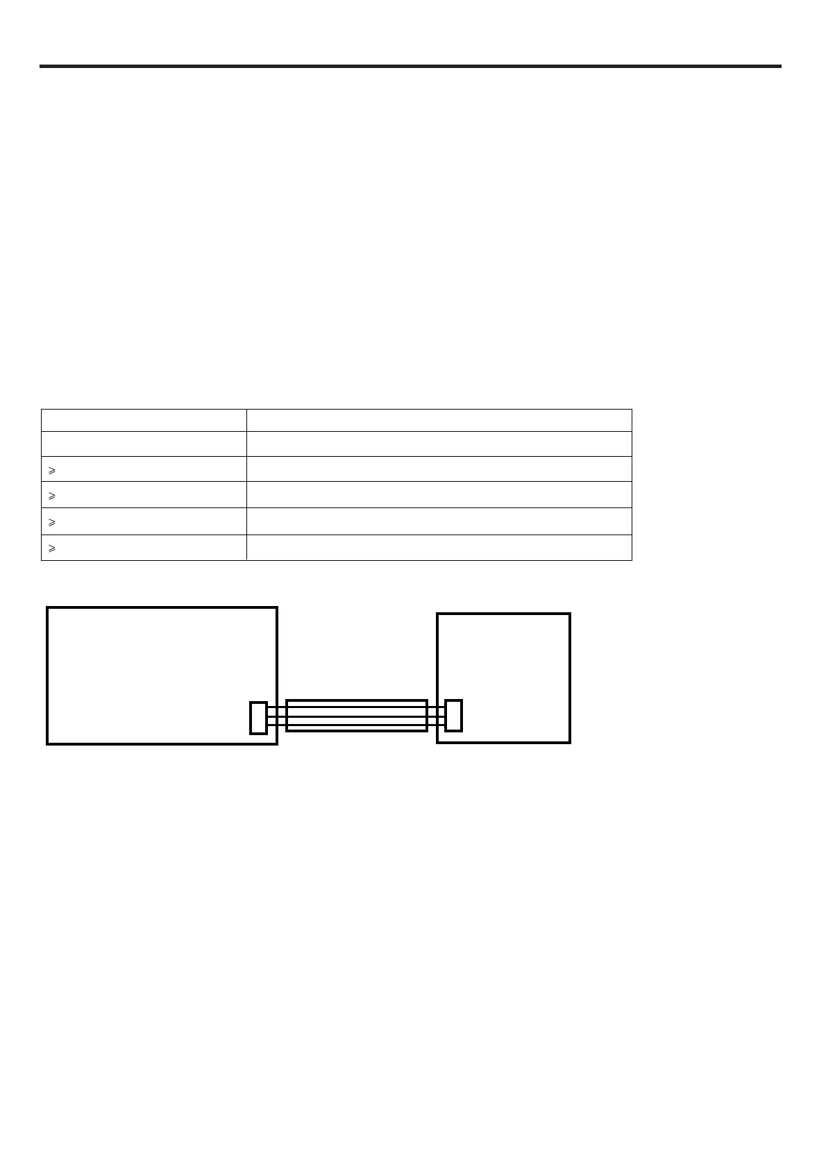
5. Wiring connections of wire controller:
WIRED CONTROLLER& INDOOR PCB CONNECTION(one for one wiring type):
.
Note:When do the wired controller & indoor PCB wiring work ,do not c
onnect the shielded wired to the
unit’s shell,do not parallel wiring with strong electric lines within 0.3 meters, please keep strong lines and the
s
ignal lines separately.
INDOOR UNIT PCB
CN22
WIRED
CONTROLLER
CON1
A
B
C
A
B
C