Avoid installation and use at those places listed below.
Places exposed to oil splashes or steam (e.g. kitchens and machine plants).
Installation and use at such places incur deteriorations in the performance or corrosion with the heat exchanger or damage
in molded synthetic resin parts.
Places where corrosive gas (such as sulfurous acid gas) or inflammable gas (thinner, gasoline etc.) in generated or
remains. Installation and use at such places cause corrosion in the heat exchanger and damage in molded synthetic
resin parts.
Places adjacent to equipment generating electromagnetic waves or high-frequency waves such as in hospitals.
Generated noise may cause malfunctioning of the controller.
NOTE
All wiring of this installation must comply with NATIONAL, STATE AND LOCAL REGULATIONS. These instructions
do not cover all variations for every kind of installation circumstance. Should further information be desired or should particular
problems occur, the matter should be referred to your local distributor.
WARNING
BE SURE TO READ THESE INSTRUCTIONS CAREFULLY BEFORE BEGINNING INSTALLATION. FAILURE TO FOLLOW
THESE INSTRUCTIONS COULD CAUSE SERIOUS INJURY OR DEATH, EQUIPMENT MALFUNCTION AND/OR
PROPERTY DAMAGE.
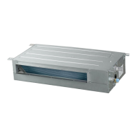
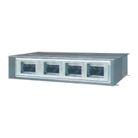
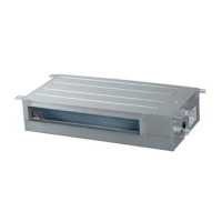
Preparation of indoor unit
Before or during the installation of the unit, assemble necessary optional panel etc. depending on the specific type.
Select places for installation satisfying following conditions and at the same time obtain the consent on the part
of your client user.
Places where chilled or heated air circulates freely. When the installation height exceeds 3m warmed air stays close to
the ceiling. In such cases, suggest your client users to install air circulators.
Places where perfect drainage can be prepared and sufficient drainage.
Places free from air disturbances to the suction port and blowout hole of the indoor unit, places where the fire alarm
may not malfunction or short-circuit.
Places with the environmental dew-point temperature is lower than 28 and the relative humidity is less than 80 %.
(When installing at a place under a high humidity environment, pay sufficient attention to the prevention of dewing such
as thermal insulation of the unit. )
Installation dimension is the following.
C
a.
b.
c.
d.
e.
a.
b.
c.
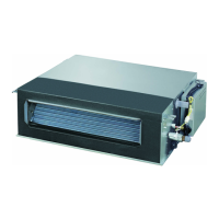
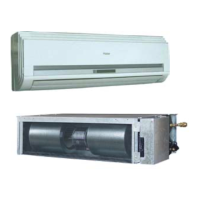
Indoor Unit
Pipe size
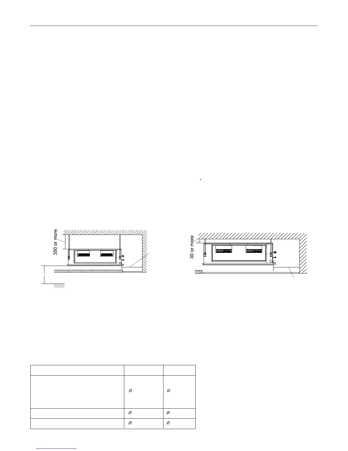
(1) Installation by which service space is made on top of the
unit (recommended)
Install the unit away from the ceiling by 350mm or more
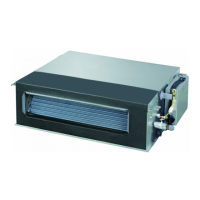
(2) Installation by which service is carried out from the bottom
of the unit
Installation Procedure
18
Model Liquid side Gas side
9.52mm 15.88mm
12.7mm 19.05mm
12.7mm 22.2mm
ADH071M1ERG ADH071M3ERG
ADH090M1ERG ADH105M1ERG
ADH125M1ERG ADH140M1ERG
ADH105H1ERG ADH125H1ERG
ADH140H1ERG ADH160H1ERG
ADH200H1ERG
ADH250H1ERG
FLOOR
2500 or more
(when no ceiling)
Service
space
500 or more
Service access
Unit:mm
Service access
500 or more
Service
space