EasyManua.ls Logo

Haier AS09/12GS2ERA User Manual

Haier AS09/12GS2ERA
84 pages
To Next Page IconTo Next Page
Page #1 background imageLoading...
Page #1 background image
SERVICE MANUAL
Order No.
EM-Series
© (Qingdao Haier Air Conditioner General corp.,Ltd)
All right reserved .Unauthorized copying and distribution is a violation of law
Haier Group
This service information is designed for experienced repair technicians only and is not designed for use by the general public.
It does not contain warnings or cautions to advise non-technical individuals of potential dangers in attempting to service a product.
Products powered by electricity should be serviced or repaired only by experienced professional technicians. Any attempt to service or
repair the product or products dealt with in this service information by anyone else could result in serious injury or death
WARNING
Wall mounted Type
DC Inverter
Model No.
AS09/12GS2ERA
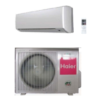
1U09/12BS1ERA outdoor unit
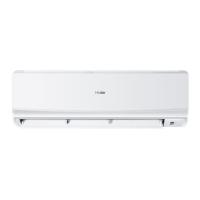
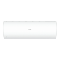
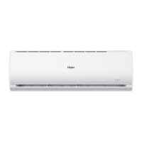
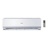
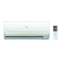
indoor unit and remote controller
AS09/12GS2ERA
1U09/12BS1ERA
Questions and Answers:

Haier AS09/12GS2ERA Specifications

General IconGeneral
BrandHaier
ModelAS09/12GS2ERA
CategoryAir Conditioner
LanguageEnglish

Summary

Haier SERVICE MANUAL

Wall mounted Type DC Inverter EM-Series

Specifies the type and series of the Haier air conditioner unit.

Model No. AS09/12GS2ERA 1U09/12BS1ERA

Identifies the specific model numbers for the indoor and outdoor units.

WARNING

Highlights critical safety warnings for product servicing and handling.

1. Introduction

1.1 Safety Cautions

Provides essential safety guidelines and warnings for repair work.

1.1.1 Caution in Repair

Details specific precautions to be observed during repair procedures.

1. Introduction

1.1.2 Cautions Regarding Products after Repair

Outlines safety considerations and warnings after the repair is completed.

1. Introduction

1.1.3 Inspection after Repair

Describes the necessary inspection steps after completing repair work.

1. Introduction

1.1.3 Inspection after Repair

Describes the necessary inspection steps after completing repair work.

Caution

Provides cautions related to installation platform, grounding, and drainage.

2. List of Functions

3 Specifications

4. Printed Circuit Board Connector Wiring Diagram

4.1: Indoor unit Connectors

Details the connectors on the indoor unit's main control PCB.

4. Printed Circuit Board Connector Wiring Diagram

4.2: outdoor unit

Details the connectors on the outdoor unit's main and module PCBs.

5.Functions and Control

5.1 Main functions and control specification of indoor unit

Describes the primary functions and control specifications of the indoor unit.

5.1.1 Automatic operation

Explains how the unit automatically selects operation modes based on room temperature.

5.Functions and Control

5.1.1 Automatic operation

Explains how the unit automatically selects operation modes based on room temperature.

5.1.2 Cooling operation mode

Details the temperature control and airflow speed settings for cooling mode.

5.1.3 Demoisture mode.

Describes the dehumidification mode, including temperature and fan speed controls.

5.Functions and Control

5.1.3 Demoisture mode.

Describes the dehumidification mode, including temperature and fan speed controls.

5.1.4 Heating operation mode.

Explains the heating mode, including temperature compensation and fan speed control.

5.Functions and Control

5.1.4 Heating operation mode.

Explains the heating mode, including temperature compensation and fan speed control.

5.1.5 strength operation

Details the strength operation mode for enhanced cooling or heating performance.

5.1.6 Mute operation

Describes the mute operation mode for quiet performance in heating or cooling.

5.Functions and Control

5.1.6 Mute operation

Describes the mute operation mode for quiet performance in heating or cooling.

5.1.7 Air refreshing

Explains the air refreshing function, including negative ion generation.

5.1.8 Timing.

Details the 24-hour on/off timing functions for operation scheduling.

5.Functions and Control

5.1.8 Timing.

Details the 24-hour on/off timing functions for operation scheduling.

5.1.9 Dormant operation

Describes the 8-hour dormant operation mode with automatic temperature adjustments.

5.Functions and Control

5.1.9 Dormant operation

Describes the 8-hour dormant operation mode with automatic temperature adjustments.

5.1.10 Urgent on/off input

Explains the urgent on/off input function and test operation procedures.

5.Functions and Control

5.1.10 Urgent on/off input

Explains the urgent on/off input function and test operation procedures.

5.1.11 Low load protection control

Details protection measures against low load conditions to prevent frosting.

5.1.12 High load protection control

Describes protection mechanisms for high load conditions to prevent overheating.

5.Functions and Control

5.1.12 High load protection control

Describes protection mechanisms for high load conditions to prevent overheating.

5.1.13 Abnormal operation of indoor system

Explains how the system handles abnormal operation between indoor and outdoor units.

5.1.14 Malfunction list resume.

Describes the procedure for resuming the malfunction list after errors.

5.Functions and Control

5.1.14 Malfunction list resume.

Describes the procedure for resuming the malfunction list after errors.

5.1.15 Abnormality confirmation approaches.

Details methods for confirming abnormalities like sensor failures or communication issues.

5.1.16 Single indoor system operation

Explains the conditions and procedure for operating a single indoor unit.

5.Functions and Control

5.1.16 Single indoor system operation

Explains the conditions and procedure for operating a single indoor unit.

5.1.17 Power cut compensation.

Describes how the system compensates for power interruptions and stores status.

5.1.18 Fixed frequency operation.

Details the fixed frequency operation for cooling and heating modes.

5.Functions and Control

5.1.18 Fixed frequency operation.

Details the fixed frequency operation for cooling and heating modes.

5.1.19 Time cutting function:

Explains the time cutting function for controlling the system's operation time.

5.Functions and Control

5.1.19 Time cutting function:

Explains the time cutting function for controlling the system's operation time.

5.2 The control system of outdoor unit

Provides an overview of the control system for the outdoor unit.

5.2.1: The operation frequency of outdoor unit and its control

Details the operation frequency control of the outdoor unit's compressor.

5.Functions and Control

5.2.1: The operation frequency of outdoor unit and its control

Details the operation frequency control of the outdoor unit's compressor.

5.2.1.1: The operation frequency control of compressor

Explains the operating frequency scope and limits of the compressor.

5.Functions and Control

5.2.1.1: The operation frequency control of compressor

Explains the operating frequency scope and limits of the compressor.

5.2.1.2: The starting of compressor

Describes the procedure for starting the compressor and its initial operation.

5.Functions and Control

5.2.1.2: The starting of compressor

Describes the procedure for starting the compressor and its initial operation.

5.2.1.3: The speeds of increasing or decreasing the frequency of the compressor

Details the speeds for increasing or decreasing compressor frequency.

5.2.1.4: The calculation of the compressor's frequency

Explains the calculation methods for compressor frequency limitations.

5.Functions and Control

5.2.1.4: The calculation of the compressor's frequency

Explains the calculation methods for compressor frequency limitations.

5.2.2: The outdoor fan control (exchange fan)

Describes the control logic for the outdoor fan, including speed changes.

5.Functions and Control

5.2.2: The outdoor fan control (exchange fan)

Describes the control logic for the outdoor fan, including speed changes.

5.2.2.1:The outdoor fan control when refrigerating or dehumidifying

Details outdoor fan control during refrigerating and dehumidifying operations.

5.Functions and Control

5.2.2.1:The outdoor fan control when refrigerating or dehumidifying

Details outdoor fan control during refrigerating and dehumidifying operations.

5.2.2.2:The outdoor fan control when heating

Explains outdoor fan control logic specifically for heating operations.

5.Functions and Control

5.2.2.2:The outdoor fan control when heating

Explains outdoor fan control logic specifically for heating operations.

5.2.3: The control of the outdoor electronic expansion valve

Describes the control mechanism for the outdoor electronic expansion valve.

5.Functions and Control

5.2.3: The control of the outdoor electronic expansion valve

Describes the control mechanism for the outdoor electronic expansion valve.

5.2.4: Four way control

Details the operation and control of the four-way valve.

5.Functions and Control

5.2.4: Four way control

Details the operation and control of the four-way valve.

5.2.5: The outdoor defrosting control

Explains the conditions and procedures for the outdoor defrosting cycle.

5.Functions and Control

5.2.5: The outdoor defrosting control

Explains the conditions and procedures for the outdoor defrosting cycle.

5.2.6 Protection function

Details various protection functions integrated into the unit's operation.

5.Functions and Control

5.2.6 Protection function

Details various protection functions integrated into the unit's operation.

5.2.6.1: TTC high temperature-preventing protection

Describes TTC protection against high temperatures for air blowing.

5.Functions and Control

5.2.6.1: TTC high temperature-preventing protection

Describes TTC protection against high temperatures for air blowing.

5.2.6.5 Antifreezing protection of the indoor heat exchanger

Explains antifreezing protection for the indoor heat exchanger.

5.Functions and Control

5.2.6.5 Antifreezing protection of the indoor heat exchanger

Explains antifreezing protection for the indoor heat exchanger.

5.2.6.2: TC high temperature-preventing control of the indoor heating unit:

Details TC control for high temperature prevention in the indoor heating unit.

5.Functions and Control

5.2.6.2: TC high temperature-preventing control of the indoor heating unit:

Details TC control for high temperature prevention in the indoor heating unit.

5.2.6.6 The frequency limitation of modification rate

Explains frequency limitations related to modification rate control.

5.2.6.8 Temperature protection of the outdoor refrigerating coil

Describes temperature protection measures for the outdoor refrigerating coil.

5.Functions and Control

5.2.6.8 Temperature protection of the outdoor refrigerating coil

Describes temperature protection measures for the outdoor refrigerating coil.

5.2.6.9: Malfunction display and malfunction handling

Details how malfunctions are displayed and handled by the system.

5.3 Value of Thermistor

5.3.1 intdoor Unit

Provides resistance values for indoor unit thermistors at various temperatures.

5.3 Value of Thermistor

5.3.1 intdoor Unit

Provides resistance values for indoor unit thermistors at various temperatures.

5.3.2 Outdoor Unit

Provides resistance values for outdoor unit sensors at various temperatures.

Operation

Base Operation

Covers fundamental operation controls and the remote controller interface.

Remote Controller

Explains the functions and usage of the remote controller buttons.

Operation

Remote Controller

Explains the functions and usage of the remote controller buttons.

Indoor Unit

Details the components and indicators of the indoor unit.

Outdoor Unit

Details the components and indicators of the outdoor unit.

Operation

Indoor Unit

Details the components and indicators of the indoor unit.

Outdoor Unit

Details the components and indicators of the outdoor unit.

Air Flow Direction Adjustment

Explains how to adjust the air flow direction manually and automatically.

Operation

Air Flow Direction Adjustment

Explains how to adjust the air flow direction manually and automatically.

Sleep Operation

Describes the sleep operation mode for energy saving and comfort.

POWER/QUIET Operation

Explains the POWER for rapid operation and QUIET for silent operation.

Operation

Sleep Operation

Describes the sleep operation mode for energy saving and comfort.

POWER/QUIET Operation

Explains the POWER for rapid operation and QUIET for silent operation.

Timer On/Off On-Off Operation

Details the timer functions for turning the unit on or off.

Healthy airflow Operation

Explains the healthy airflow function and its settings.

Installation

Indoor Unit Installion

Provides instructions and diagrams for installing the indoor unit.

Necessary Tools for Installation

Lists the essential tools and materials required for installation.

Installation

Indoor Unit Installion

Provides instructions and diagrams for installing the indoor unit.

Necessary Tools for Installation

Lists the essential tools and materials required for installation.

1 Fitting of the Mounting Plate and Positioning of the wall Hole

Details the process of fitting the mounting plate and locating the wall hole.

2 Making a Hole on the Wall and Fitting the Piping Hole Cover

Explains how to make the wall hole and fit the piping hole cover.

Installation

2 Making a Hole on the Wall and Fitting the Piping Hole Cover

Explains how to make the wall hole and fit the piping hole cover.

3 Installation of the Indoor Unit

Provides step-by-step instructions for installing the indoor unit body.

4 Connecting the indoor/outdoor Electric Cable

Details the procedure for connecting the electrical cables between units.

Maintenance

For Smart Use of The Air Conditioner

Offers tips for smart usage, including temperature, cleaning, and timer settings.

Cautions

WARNING

Highlights critical warnings regarding installation and operation safety.

Trouble shooting

Before asking for service, check the following first.

Provides initial checks for common phenomena before requesting service.

Specifications

Lists applicable ambient temperature ranges for unit operation.

7 Service Diagnosis

7.1 Caution for Diagnosis

Provides cautions to be followed before proceeding with diagnosis.

7.2.Problem Symptoms and Measures

Lists common problem symptoms and their corresponding diagnostic measures.

7 Service Diagnosis

7.2.Problem Symptoms and Measures

Lists common problem symptoms and their corresponding diagnostic measures.

7.3.Error Codes and Description indoor display

Details error codes and their descriptions for indoor and outdoor units.

7 Service Diagnosis

7.3.Error Codes and Description indoor display

Details error codes and their descriptions for indoor and outdoor units.

7.3.1 Thermistor or Related Abnormality (indoor unit)

Diagnoses thermistor abnormalities in the indoor unit.

7 Service Diagnosis

7.3.1 Thermistor or Related Abnormality (indoor unit)

Diagnoses thermistor abnormalities in the indoor unit.

7.3.2 Indoor fan motor malfunction

Diagnoses malfunctions related to the indoor fan motor.

7 Service Diagnosis

7.3.2 Indoor fan motor malfunction

Diagnoses malfunctions related to the indoor fan motor.

7.3.3 IPM protection

Explains IPM protection mechanisms and troubleshooting steps.

7 Service Diagnosis

7.3.3 IPM protection

Explains IPM protection mechanisms and troubleshooting steps.

7.3.4 The IPM and outdoor PCB don't communicate or Related Abnormality

Diagnoses communication failures between IPM module and outdoor PCB.

7 Service Diagnosis

7.3.4 The IPM and outdoor PCB don't communicate or Related Abnormality

Diagnoses communication failures between IPM module and outdoor PCB.

7.3.5 Thermistor or Related Abnormality(outdoor unit)

Diagnoses thermistor and related abnormalities in the outdoor unit.

7 Service Diagnosis

7.3.5 Thermistor or Related Abnormality(outdoor unit)

Diagnoses thermistor and related abnormalities in the outdoor unit.

7.3.6 Overheat Protection For Exhaust Temperature

Details overheat protection for exhaust temperature and its troubleshooting.

7 Service Diagnosis

7.3.6 Overheat Protection For Exhaust Temperature

Details overheat protection for exhaust temperature and its troubleshooting.

7.3.7 The EEPROM Abnormality (Indoor or outdoor unit)

Diagnoses EEPROM abnormalities in indoor or outdoor units.

7 Service Diagnosis

7.3.7 The EEPROM Abnormality (Indoor or outdoor unit)

Diagnoses EEPROM abnormalities in indoor or outdoor units.

7.3.8 Communication error between the indoor and outdoor units

Addresses communication errors between indoor and outdoor units.

7 Service Diagnosis

7.3.8 Communication error between the indoor and outdoor units

Addresses communication errors between indoor and outdoor units.

7.3.10 Power Supply Over or under voltagve fault

Diagnoses power supply voltage faults (over or under voltage).

7 Service Diagnosis

7.3.10 Power Supply Over or under voltagve fault

Diagnoses power supply voltage faults (over or under voltage).

7.3.11 Loop of the station detect error

Addresses errors related to detecting the compressor rotor position.

7 Service Diagnosis

7.3.11 Loop of the station detect error

Addresses errors related to detecting the compressor rotor position.

7.3.12 Over-current of the compressor

Diagnoses and resolves over-current issues with the compressor.

Installation

Installation Manual of Room Air Conditioner

Provides comprehensive instructions for installing the air conditioner.

EUROPEAN REGULATIONS CONFORMITY FOR THE MODELS

Lists European conformity regulations applicable to the product models.

IMPORTANT INFORMATION REGARDING THE REFRIGERANT USED

Provides critical information about the R410A refrigerant used in the unit.

Installation

Installation Manual of Room Air Conditioner

Provides comprehensive instructions for installing the air conditioner.

Safety Precautions

Details safety precautions for operating and installing the air conditioner.

Installation

Safety Precautions

Details safety precautions for operating and installing the air conditioner.

Precautions for Handling Units for Use with R410A

Provides specific handling precautions for units using R410A refrigerant.

Installation

Precautions for Handling Units for Use with R410A

Provides specific handling precautions for units using R410A refrigerant.

Before Installing the Unit

Covers precautions and checks required before the initial installation.

Installation

Before Installing the Unit

Covers precautions and checks required before the initial installation.

Read Before Installation

Provides essential information and checks before proceeding with installation.

Piping Materials

Details specifications and requirements for piping materials.

Installation

Piping Materials

Details specifications and requirements for piping materials.

Flare Machining (type-O and OL only)

Specifies flare machining dimensions for R410A units.

Flare Nut

Details specifications for flare nuts used in R410A installations.

Installation

Flare Nut

Details specifications for flare nuts used in R410A installations.

Read Before Installation

Provides essential information and checks before proceeding with installation.

Air Tightness Test

Explains the procedure for conducting the air tightness test.

Installation

Air Tightness Test

Explains the procedure for conducting the air tightness test.

1. Accessories

Lists the accessories included with the unit for installation.

2. Selection of the place of installation

Guides on selecting an appropriate location for unit installation.

Installation

2. Selection of the place of installation

Guides on selecting an appropriate location for unit installation.

1. Piping size

Specifies the required sizes for refrigerant piping.

2. Connection of pipes

Provides instructions for connecting the refrigerant pipes.

Installation

2. Connection of pipes

Provides instructions for connecting the refrigerant pipes.

Installation

WARNING!

Reinforces critical warnings about electrical connections and safety.

Precautions for Electrical wiring

Details safety precautions and requirements for electrical wiring work.

Selection of size of power supply and interconnecting wires

Specifies wire sizes and circuit protection for power supply and connections.

Installation

Selection of size of power supply and interconnecting wires

Specifies wire sizes and circuit protection for power supply and connections.

Outdoor Unit Troubleshooting

Provides troubleshooting steps for common issues with the outdoor unit.

Related product manuals