Wiring diagrams
11 Domestic air conditioner
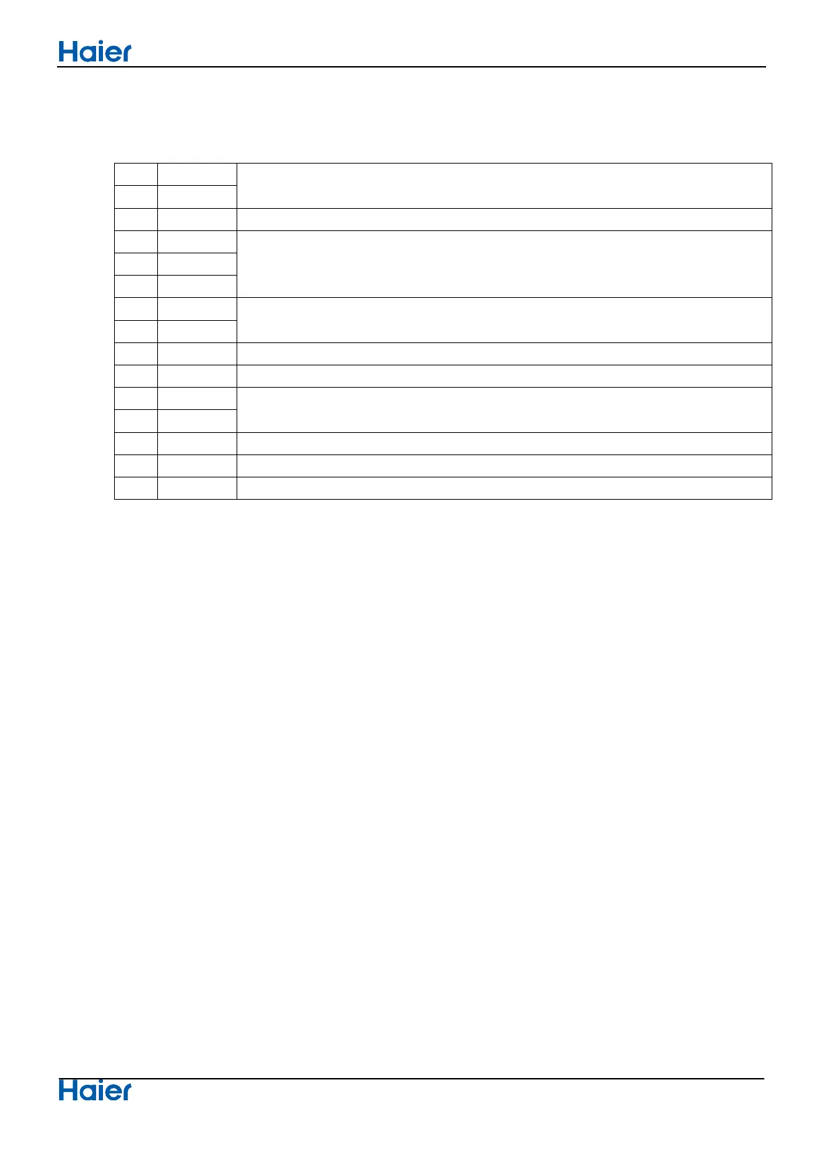
6.Printed Circuit Board Connector Wiring Diagram
Connectors
PCB (1) (Outdoor Control PCB)
1 CN1
Connector for power N and
●
L
2 CN2
3 CN3 Connector for ground
4 CN2’
Connector for the U, V, W wire of the
compressor 5 CN3’
6 CN4’
7 LI (CN7)
Connector for reactor
8 LO (CN6)
9 CN21 Connector for fan motor
10 CN10 Connector for four way valve coil
11 CN20
Connector for Temperature sensor
12 CN18
13 CN5 Connector for Terminal Socket-protection
14 CN4 Connector for communicate between indoor and outdoor unit
15 CN16 Connector for electric expansion valves
Note: Othe
r Designations
●
1) FUSE 1, (2
0A, 250VAC); FUSE 2(3.15A, 250V
AC)
2) LED 1 Kee
p light representative normal, if keep flash interval representative trouble Alarm
3) R
V1, RV2, RV3, RV4 Varistor
 Loading...