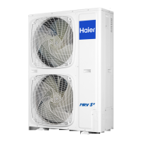
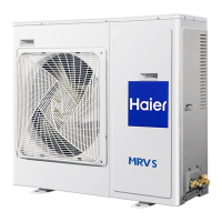
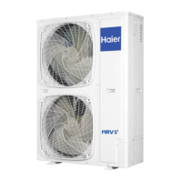
Do you have a question about the Haier AU07NFPEUA and is the answer not in the manual?
Conforms to European Low Voltage, EMC, RoHS, and WEEE directives.
Details the R410A refrigerant type, GWP, and charge label instructions.
Highlights warnings for installation and maintenance causing death or serious injury.
Lists prohibited actions and cautions to prevent serious accidents.
Provides further safety precautions for installation and operation.
Lists specific tools required for working with R410A refrigerant.
Procedures for inspecting the unit upon arrival for damage and correctness.
Guidelines for safely lifting the outdoor unit using ropes and proper methods.
Detailed steps for hoisting and manual handling, ensuring safety.
Pre-installation checks of models, power supply, piping, and unit compatibility.
Guidance on selecting a suitable installation location for the outdoor unit.
Important notes regarding installation in various environments and noise.
Specifies the required installation and maintenance space for unit setups.
Details installation space for multi-unit configurations in front and back.
Precautions for installation, including foundation work and wind protection.
Method and cautions for connecting refrigerant pipes, including welding and cleaning.
Guidelines for selecting appropriate refrigerant pipe material and specifications.
Instructions for proper drain pipe installation and disposal.
Specifications for pipe diameters and copper pipe selection.
Illustrates piping connection methods from different directions and connection points.
Permissible limits for refrigerant piping length and height differences.
Details unit pipe specifications and connection methods for outdoor and indoor units.
Guidance on selecting branch pipes based on unit capacity.
Explains the necessity and methods for heat insulation of refrigerant pipes.
Instructions on how to fix refrigerant pipes to prevent vibration and stress.
Steps for connecting pipes, bending, expanding, and flaring for R410A.
Procedure for performing a refrigerant leakage test using nitrogen gas.
Steps for evacuating the system to remove air and moisture using a vacuum pump.
Instructions on opening and closing service valves, including torque specifications.
Method for charging additional refrigerant, including calculation and procedures.
Critical warnings and cautions regarding electrical safety and connections.
Illustrates the communication wiring configuration between outdoor and multiple indoor units.
Instructions for connecting power cords, ground wires, and communication lines.
Diagram showing the power wiring connections for the outdoor and indoor units.
Specifies power source, cable size, circuit breaker, and ground wire for the outdoor unit.
Details power supply and communication wiring requirements for indoor units.
Specifications for signal line length, wiring dimensions, and shielding for wired controllers.
Detailed diagram showing electrical connections within the outdoor unit.
Illustrates correct and incorrect methods for terminal connections.
Explains digital tube display codes for faults, operations, and special states.
Lists and defines various sensors used in the outdoor unit.
Details the forced refrigeration mode activation and deactivation.
Continuation of digital tube display codes for outdoor unit operation and faults.
Displays parameters related to the supercooling valve plate, including failures and temperatures.
Instructions for setting outdoor unit PCB dipswitches for various functions.
Details BM1/BM2 settings for unit searching, modes, and power selection.
Information on bridge (jumper) settings for factory production and time function adjustment.
Lists common failure codes for the outdoor unit, definitions, and remarks.
Details failures related to sensors and indoor communication.
Covers failures like valve issues, protection triggers, and compression ratio problems.
Failures related to high pressure, discharging temp, and communication sensors.
Failures concerning CT current sensors and valve plate module communication.
Failures related to DC motors, pressure drops, and IPM module overheating.
Failures concerning transducers, voltage issues, and control circuit abnormalities.
Failures related to transducers, compressor startup, and IPM module faults.
Lists standby codes and common failure codes for indoor units.
Verifying unit type, count, and power before operation.
Explains unit operation modes and defrosting characteristics.
Details protection device activation and unit behavior during power failures.
Detailed steps for performing trial operation, including checks and valve operation.
Guidance on relocating the unit and environmental disposal requirements.
| Brand | Haier |
|---|---|
| Model | AU07NFPEUA |
| Category | Air Conditioner |
| Language | English |


