Do you have a question about the Haier InoSens MRV SI AU032FSEUA and is the answer not in the manual?
| Cooling Capacity | 3.2 kW |
|---|---|
| Heating Capacity | 3.6 kW |
| Refrigerant | R32 |
| Outdoor Unit Noise Level | 50 dB(A) |
| Cooling Capacity (kW) | 3.2 |
| Heating Capacity (kW) | 3.6 |
| Outdoor Unit Weight | 30 kg |
| Power Supply | 220-240V, 50Hz |
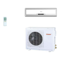
Lists various indoor unit types and their models.
Critical safety warnings for high-voltage components within the control box.
Explains dial code settings and symbols used in wiring diagrams.
Essential steps and checks before initial operation and trial runs.
Graphs showing capacity adjustments based on indoor/outdoor conditions.
Graphs showing capacity adjustments for heating based on conditions.
Compensation values based on piping configuration and height differences.
Graph showing capacity compensation for defrosting function.
Tables providing correction factors for piping length and height drop.
Defines the operating limits for cooling mode based on indoor/outdoor temperatures.
Defines the operating limits for heating mode based on indoor/outdoor temperatures.
Details testing methodology and conditions for measuring noise levels.
Graphs illustrating sound pressure levels across different frequency bands.
Essential safety guidelines to prevent hazards during installation.
Step-by-step guide for unit installation and site selection.
Methods and precautions for safely moving and handling the outdoor unit.
Specific procedures for manual transport and placement of the unit.
Important safety and procedural guidelines to follow during installation.
Specifies clearance and space requirements for single and multi-unit installations.
Guidelines for ensuring a stable and secure installation base for the unit.
Methods to prevent fan reversal or damage from strong winds.
Methods, cautions, materials, and procedures for connecting refrigerant pipes.
Guidelines for selecting correct pipe diameters, lengths, and specifications.
Proper insulation and securing techniques for refrigerant pipes.
Steps for performing a refrigerant leakage test.
Process for removing air and moisture from the refrigerant system.
Rules and specifications for indoor unit power supply and communication wiring.
Specifications for outdoor unit power supply, cable, and grounding.
Electrical wiring diagram for outdoor units with a single fan.
Electrical wiring diagram for outdoor units with double fans.
Explanation of BM1 dip switch functions and their settings.
How to view system status and perform master unit controls.
Procedures for displaying and setting E2 control parameters.
Guidelines for controlling compressor startup based on various conditions.
Methods for controlling compressor frequency for optimal capacity output.
Logic and conditions for activating and deactivating defrosting cycles.
Procedures and conditions for managing oil return to the compressor.
A list of failure codes for inverter outdoor units and their definitions.
Troubleshooting flowcharts for various specific failure codes and symptoms.
Table listing sensor types and their basic characteristics.
Detailed resistance values for sensors at various temperatures.