EasyManua.ls Logo

Haier 1U15AP2VHA User Manual

Haier 1U15AP2VHA
186 pages
To Next Page IconTo Next Page
Page #1 background imageLoading...
Page #1 background image
Ductless Split Heat Pump
Service Manual
Design may vary by model number.
Please read this manual before using the heat pump.
Keep this user manual for future reference.
PAGE 1
Safety Precautions/Introduction .................................................................................................3
Outdoor Unit Controls and Components ..................................................................................... 7
Indoor Unit Controls and Components ......................................................................................15
Sequence Of Operation ............................................................................................................. 21
Error Codes and Problem Solving ..............................................................................................29
Reference Information ..............................................................................................................43
Table of Contents
Indoor
AW09ES2VHB
AW12ES2VHB
AW15ES2VHB
AW18ES2VHB
AW24ES2VHB
Outdoor
1U09AP2VHA
1U12AP2VHA
1U15AP2VHA
1U18AP2VHA
1U24AP2VHA

Table of Contents

Other manuals for Haier 1U15AP2VHA

Question and Answer IconNeed help?

Do you have a question about the Haier 1U15AP2VHA and is the answer not in the manual?

Haier 1U15AP2VHA Specifications

General IconGeneral
BrandHaier
Model1U15AP2VHA
CategoryAir Conditioner
LanguageEnglish

Summary

Safety Precautions and System Introduction

Safety Precautions

General safety rules and warnings for installation and operation.

Introduction to System

Overview of the ductless split heat pump system features and design.

Fundamental Theory of System Operation

Explains the basic principles of how the heat pump system functions.

Outdoor Unit Controls and Components

Outdoor Unit Introduction and Identification

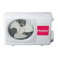
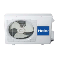
Overview and visual identification of the outdoor unit's main parts.

Outdoor Control Board Components

Detailed information on the outdoor control board PCBs and connectors.

Terminal Block, Compressor, Fan Motor, Reactor

Descriptions of Terminal Block, Compressor, Fan Motor, and Reactor.

Outdoor Unit Temperature Sensors

Details on Discharge, Defrost, Ambient, and Suction line sensors.

Outdoor Unit Refrigerant and Heating Components

Information on 4-Way Valve, EEV, Accumulator, Filters, and Base Pan Heater.

Outdoor Unit DIP Switch Settings

Configuration settings for the outdoor unit's DIP switches.

Indoor Unit Controls and Components

Indoor Unit Introduction and Identification

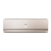
Overview and visual identification of the indoor unit's main parts.

Indoor Control Board Components

Detailed information on the indoor control board and its connectors.

Indoor Unit Interfaces and Sensors

Details on Terminal Block, Display, Ambient, and Coil temperature sensors.

Indoor Unit Motors and Controls

Information on Louver Motor, Fan Motor, and Emergency Button.

Indoor Unit DIP Switch Settings

Configuration settings for the indoor unit's DIP switches.

Sequence of Operation

System Power and Cool Mode Operation

How the system powers up and operates in cooling mode.

Heat Mode Operation

Details on system operation during heating mode.

Auto and Dry Mode Operations

Operation modes for Auto (switching) and Dry (dehumidification).

Defrost Operation and Protection Functions

How defrost cycles work and system protection mechanisms.

Error Codes and Problem Solving

Indoor Unit Error Codes and Malfunctions

Summary of indoor unit error codes and general malfunctions.

Outdoor Unit Fan Motor Faults

Troubleshooting steps for outdoor DC fan motor failures.

Outdoor Unit Protection and Overcurrent Errors

IPM Protection and Compressor Overcurrent error codes.

Outdoor Unit Communication and Power Supply Errors

Communication faults (IPM/PCB) and power supply voltage issues.

Discharge Temperature and System Communication Errors

Overheat protection for discharge temp and Indoor/Outdoor comm faults.

Loss of Synchronism and Indoor Overload Errors

Synchronism detection issues and indoor unit overload in heating mode.

Troubleshooting Outdoor Unit Components

Procedures for checking outdoor unit components' resistance and function.

Troubleshooting Indoor Unit Components

Procedures for checking indoor unit components' resistance and function.

Optimizing Performance and Cleaning

Tips for optimizing performance and cleaning the unit.

Troubleshooting Tips and Common Problems

Common issues like restart delays, noise, odors, and poor cooling.

Reference Information

Outdoor Unit Diagrams and Schematics

Wiring diagrams and schematics for the outdoor control board.

Indoor Unit Diagrams and Schematics

Wiring diagrams and schematics for the indoor control board.

Module Board Schematic

Schematic diagram for the module control board.

Room and Pipe Sensor Data Tables

Resistance values for room and pipe sensors at various temperatures.

Ambient, Defrost, and Pipe Sensor Data Tables

Resistance values for ambient, defrost, and pipe sensors at various temperatures.

Discharge Sensor Data Tables

Resistance values for discharge sensors at various temperatures.

Related product manuals