19
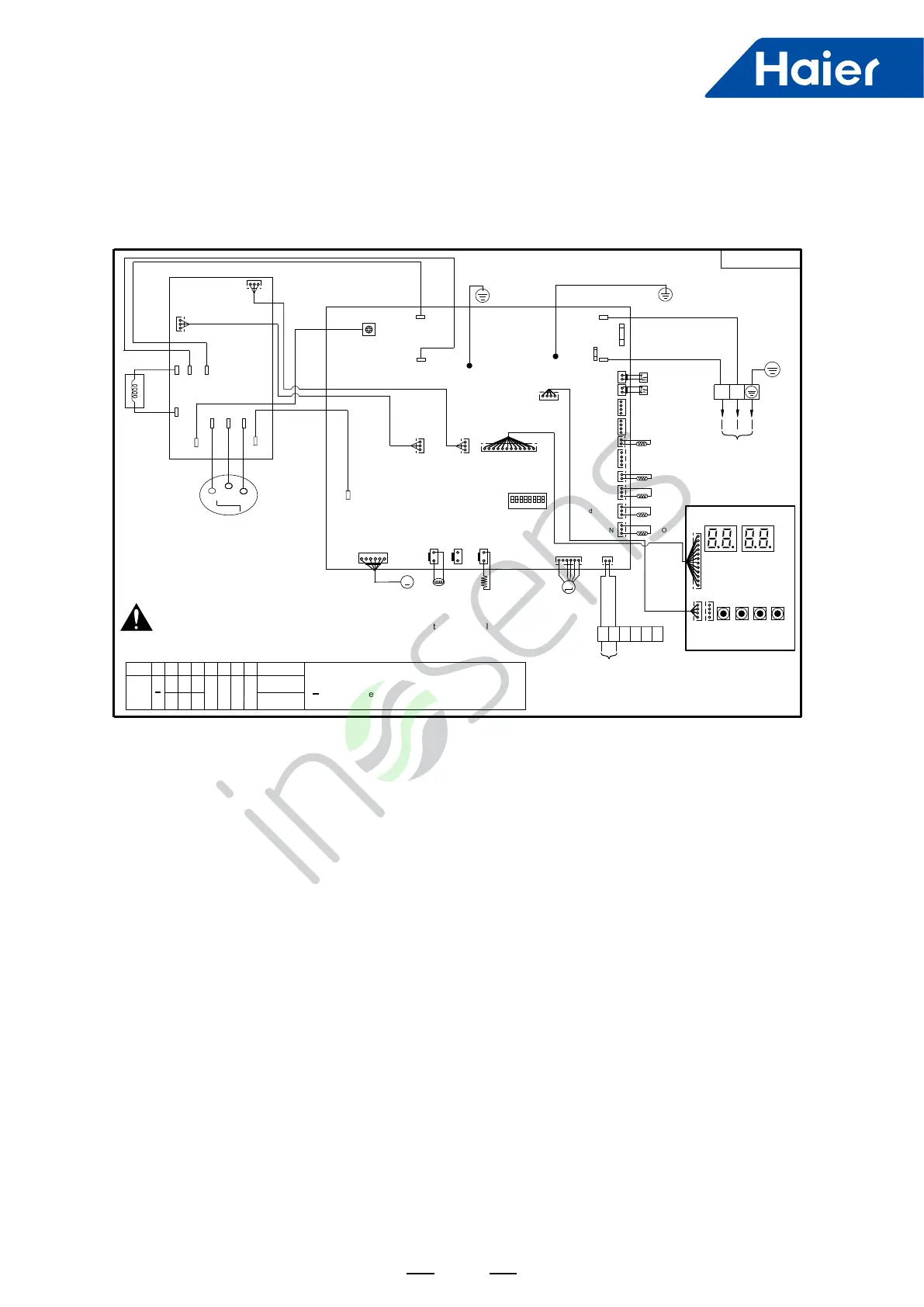
7. Wiring Diagram
CN37
CN34
T25A/250VAC
FUSE1
CN13
CN15
L N
CN9
red
blue
W
U
compressor
red
V
black white
yellow/green
red
blue
377AC module
reactor
AC-L
AC-N
U
W
V
blue CN10
blue
red
white
N
P
CN19
CN27
black CN11
N-OUT
L-OUT
AC-N
PE
HPS
AC-L
CN35
PE
yellow/green
blue
red
LPS
CN1
CN2
red
white
CN29
CN28
blue
CN23
CN4
blue
TE(1)
CN6
CN7
TAO
TS
yellow
black
white
P Q
red CN21
indoor communication
outdoor power supply
LEVA1
M
red CN8
BM1
NO
1 2 3 4 5 6 7 8
CN16
CN17 CN25
HEATER4WV
green
yellowwhite
CN12
DC-FAN
white
blue CN33 white CN10
LO
LI
INV-POWER
white CN24
【Wiring Diagram】
white CN1
SMG1
SMG2
SW4 SW5 SW6 SW7
UP DOWN EXIT ENTER
blue CN2-1
white
CN2
red CN40
394 main control board
405 display board
【High Voltage Warning】
The control box is equipped with high-voltage components
Please turn off the power and keep the unit shut down for more than 10 minutes and ensure that
voltage between P and N on the frequency conversion board is reduced to DC 20V or less
before checking the inside of the control box.
P
CN3 Td1
red
CN5
white
TC
black
white
black
white
white
T25A/250VAC
FUSE1
T3.15A/250VAC
FUSE2
AG B
12V
yellow/green
red
[1] [2] [3] [4] [5] [6] [7] [8]
-
0 0
0 0 0 0BM1
dial model
【Dial Code Description 】
0 0 1
0
O represent OFF
1 represent ON
-
represent need to be setting when installing
3.0
M
0150541650
3.5
AU032FSEUA

 Loading...