Do you have a question about the Haier AU252XGERA and is the answer not in the manual?
Introduction to the Haier X Multi commercial air conditioner service manual.
Overview of the Haier X Multi series product range and models.
Details on the operating temperature limits for cooling and heating modes.
Information on self-diagnosis, central control, and adjustable heating compensation.
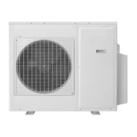
Detailed technical specifications for the outdoor units.
Technical specifications for the Haier AU222XFERA outdoor unit.
Technical specifications for the Haier AU252XGERA outdoor unit.
Technical specifications for the Haier AU282XHERA outdoor unit.
Technical specifications for the Haier AU342XHERA outdoor unit.
Technical specifications for the Haier AU362XHERA outdoor unit.
Technical specifications for Haier AS series outdoor units.
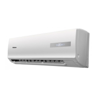
Technical specifications for Haier AB series indoor units.
Technical specifications for Haier AD series indoor units.
Technical specifications for Haier AC series indoor units.
Technical specifications for Haier AF series indoor units.
Physical dimensions of AU182XFERA and AU222XFERA outdoor units.
Physical dimensions of the AU252XGERA outdoor unit.
Physical dimensions of the AU282XHERA outdoor unit.
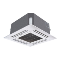
Physical dimensions of the cassette indoor unit.
Physical dimensions of the convertible indoor unit.
Physical dimensions of the ceiling concealed indoor unit.
Physical dimensions of the console indoor unit.
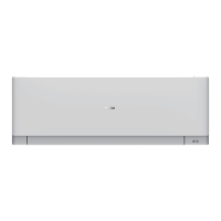
Physical dimensions of the wall mounted indoor unit.
Performance data for various indoor/outdoor unit cooling combinations.
Performance data for various indoor/outdoor unit heating combinations.
Performance data for AU222XFERA cooling and heating combinations.
Performance data for AU252XGERA cooling combinations.
Performance data for AU252XGERA heating combinations.
Performance data for AU282XHERA cooling combinations.
Performance data for AU282XHERA heating combinations.
Performance data for AU342XHERA cooling combinations.
Performance data for AU342XHERA heating combinations.
Performance data for AU362XHERA cooling combinations.
Performance data for AU362XHERA heating combinations.
Wiring diagram for the AU18-222XFERA model.
Wiring diagram for the AU25-342X*ERA model.
Wiring diagram for the AU362XHERA model.
Piping and installation limitations for AU182XFERA/AU222XFERA models.
Piping length and drop limitations for AU28-342XHERA models.
Piping length and drop limitations for AU362XHERA models.
Diagrams illustrating the installation of indoor and outdoor units.
Steps for performing refrigerant piping work, including selection and connection.
Detailed steps for connecting refrigerant pipes, including fastening torque.
Instructions for attaching the drain-elbow component.
Procedures for cutting and flaring refrigerant pipes, including correct and incorrect methods.
Proper methods for installing the unit's drain hose and ensuring correct drainage.
Procedure for purging the system using a vacuum pump.
Guidelines and standards for electric wiring, including safety precautions.
Methods for connecting wires to terminals using ring and straight terminals.
Steps for wiring the outdoor unit's power and communication lines.
Steps for wiring the indoor unit's power and communication lines.
Items to check and confirm before starting the system test run.
List of tools needed for cassette type unit installation.
List of self-contained accessories for installation.
Guidelines for selecting the optimal installation location for cassette units.
Steps for installing the cassette indoor unit, including ceiling considerations.
Instructions for installing the water drainage pipe for cassette units.
Steps for installing and securing the drain hose for cassette units.
Specifications for drainage hose installation and routing.
Diagrams and dimensions for piping connection of AC series units.
Dimensions for connecting pipes used in AC series units.
Important cautions regarding piping connection to prevent damage and leakage.
Detailed methods for electrical wiring, including terminal connections.
Specific wiring diagrams and notes for indoor units.
Procedure for setting communication addresses for indoor units via remote.
Method to verify the set indoor unit communication addresses.
Guidelines for choosing the optimal mounting location for convertible units.
Factors to consider when mounting the indoor unit for convertible types.
Steps for preparing the installation of floor console type indoor units.
Instructions for drilling holes for piping on the wall for floor console units.
Steps for installing the drain hose for floor console type units.
Procedure for installing indoor units designed for under-ceiling mounting.
Instructions for drilling holes for piping in under-ceiling installations.
Procedure for drilling and installing anchor bolts for unit mounting.
Steps for installing mounting brackets for under-ceiling units.
Final steps for mounting the indoor unit onto installed brackets.
Instructions for installing drain hose for under-ceiling and outdoor units.
Procedures for connecting piping to the outdoor unit.
Steps for performing flare processing on refrigerant pipes.
Guidelines for bending refrigerant pipes without causing damage.
Details on piping connection for AC142/AC182XCERA models.
Important cautions regarding refrigerant piping connections.
Methods and torque specifications for connecting refrigerant pipes.
Methods for connecting electrical wires to terminals (solid and strand).
How to fasten connection cords and power cables using a cord clamp.
Detailed procedures for electrical wiring of the indoor unit.
Steps to access and remove the indoor unit's electric component box.
Step-by-step guide for wiring the indoor unit's components.
Specifics on wiring indoor units, including cable types and distances.
Procedure for setting communication addresses for indoor units via remote.
Procedure for setting indoor unit addresses using DIP switches SW01 and SW03.
Procedure to check and verify indoor unit addresses set via remote.
How to set temperature compensation for heating mode using the remote controller.
Procedures and precautions for outdoor unit electrical wiring.
Information to provide to the customer regarding unit operation and maintenance.
Steps for mounting the unit's cover plates and intake grill.
Instructions for mounting the right-side cover plate.
Instructions for mounting the left-side cover plate.
Steps for attaching the intake grill to the indoor unit.
Tools and accessories needed for installing duct type indoor units.
List of self-contained accessories for duct type unit installation.
Guidelines for selecting the optimal installation location for duct type units.
Steps for installing duct type indoor units, including wall penetration.
Instructions for installing the air discharge duct for duct type indoor units.
Steps for connecting the air return duct to the indoor unit.
Proper insulation methods for air supply and return ducts.
Requirements and guidelines for installing the indoor unit drain pipe.
Specifications for pipes and insulation materials used in the system.
Instructions for installing and insulating the unit's hose.
Limits on pipe length and height difference for optimal system performance.
Details on adding supplementary refrigerant, including type and procedure.
Methods for cutting and expanding refrigerant pipes correctly.
Dimensions for pipe expansion based on diameter.
Torque specifications for connecting indoor unit pipes using double spanners.
Procedure for setting indoor unit communication addresses using DIP switches.
Checks and procedures for verifying correct installation and initial operation.
Checklist for confirming correct installation of system components.
Steps for conducting a trial operation of the air conditioning system.
Methods for connecting electrical wires to terminals using ring, straight terminals, and crimping.
Specific wiring diagrams and notes for indoor units.
Guidelines for selecting the installation location for console type indoor units.
Criteria for choosing the optimal location for console type indoor units.
Steps for securely fixing the indoor unit.
Procedures for determining and creating the wall hole for piping.
Diagrams and procedures for connecting piping to console units.
Important cautions for connecting refrigerant pipes to console units.
Detailed steps for the pipe connection process, including alignment.
Arrangement of piping and drain hose for indoor unit connections.
Proper routing and slope requirements for the drain hose.
Steps for connecting electrical wires to the indoor unit terminals.
Essential requirements for the power supply connection.
General procedures for cutting and flaring pipes, with inspection checklist.
Checklist for installation inspection and test run procedures.
Specific wiring diagrams and notes for indoor units.
Diagram illustrating wiring connections for indoor units.
Setting communication addresses for indoor units using the remote controller.
Procedure for setting indoor unit addresses using DIP switches SW01 and SW02.
Method to verify indoor unit addresses set via DIP switches.
Safety precautions and electrical warnings for wall mounted unit installation.
Tools and accessories needed for wall mounted unit installation.
List of self-contained accessories for wall mounted unit installation.
Guidelines for selecting the optimal installation location for wall mounted units.
Methods for cutting and expanding pipes, including correct and incorrect examples.
Steps for properly fixing the mounting plate to the wall.
Procedure for creating a wall hole and fitting the piping cover.
Guidelines for routing pipes based on installation direction.
Setting indoor unit addresses using the remote controller.
Method to verify indoor unit addresses set via DIP switches.
Final checks and trial operation procedures for the installed system.
Checklist for confirming correct installation of system components.
Steps for performing a trial operation to test system functionality.
Visual identification of components on the outdoor unit's main PCB.
Detailed wiring diagram for the AU182XFERA outdoor unit.
Detailed wiring diagram for the AU252XGERA outdoor unit.
Wiring diagrams for AU282XHERA and AU342XHERA outdoor units.
Detailed wiring diagram for the AU362XHERA outdoor unit.
Description of functions for SW5 DIP switches on the outdoor unit PCB.
Defines the functions of SW5 DIP switches on the failure indicator board.
Schematic diagrams of pipe systems for different unit combinations.
Control logic for outdoor unit frequency based on operating conditions.
Electronic Expansion Valve (EEV) control parameters and logic.
Procedures for EEV initialization and open angle limitations.
Control logic for EEV open angle based on ambient and discharge temperatures.
Operation logic for the 4-way valve during heating mode.
Control logic for the electric heater to prevent compressor oil freezing.
Control logic for the liquid spray valve based on compressor temperature.
Conditions and logic for initiating and canceling defrosting operations.
Flowchart illustrating the defrosting operation sequence.
Logic for controlling compressor frequency to manage high discharge temperatures.
Frequency control logic to prevent over current protection.
Mechanism and logic for high pressure protection in the system.
Mechanism and logic for low pressure protection in the system.
Detailed explanation of low pressure protection logic and conditions.
Visual identification of components on the indoor unit PCB for AB and AD series.
Wiring diagram for AB and AD series indoor units.
Wiring diagram for AD series indoor units.
Visual identification of components on the AC142-182XCERA indoor unit PCB.
Wiring diagram for the AC142-182XCERA indoor unit.
Control functions related to dip switches for cassette and convertible indoor units.
Detailed functions of SW01 dip switches for electrical control.
Detailed functions of SW02 dip switches for electrical control.
Detailed functions of SW03 dip switches for electrical control.
Definitions and meanings of various sensors used in the system.
Explanation of Dry, Fan, and Auto operation modes.
Procedures for handling abnormal operations and system errors.
Controls for anti-cold air, fan motor in defrosting, and swing motor.
Control logic for water pump and compulsory defrosting operations.
Procedures for trial operation and using the timer function.
Description of the sleep function for controlling temperature overnight.
Features related to negative ion generation and auto-restart capability.
Information on passive contact function and setting indoor unit numbers.
Detailed sensor definitions and explanation of operation modes (Dry, Fan, Auto).
Logic and conditions for Auto, Cooling, and Heating operation modes.
Explanation of anti-freeze and overload protection mechanisms.
Visual identification of components on the AF092-122XCERA indoor unit PCB.
Wiring diagram for the AF092-122XCERA indoor unit.
Detailed functions of SW01 and SW02 dip switches for electrical control.
Functions of electrical PCBs for console and cassette type units.
Visual identification of components on the AS series indoor unit PCB.
Wiring diagram for AS07/09/122XVERA indoor units.
Wiring diagram for the AS182XVERA indoor unit.
Description of functions for wall mounted indoor units.
SW01 dip switch settings for wall mounted unit functions.
SW02 dip switch settings for wall mounted unit functions.
SW02 dip switch settings for AS092XCERA unit.
SW01/SW02 dip switch settings for AS122XCERA unit.
Logic for cooling, dry, and fan modes, including abnormal operations.
Logic for heating mode, including abnormal operations.
Details on anti-freeze and overload protection for wall mounted units.
Control logic for swing motor and water pump operations.
Procedures for compulsory defrosting and trial operation.
Functions for timer, sleep, and setting the indoor unit communication number.
Method for setting temperature compensation in cooling and heating modes.
Error codes and potential causes for AU series units.
Error codes and potential causes for AB and AC series units.
Error codes and potential causes for AD series units.
Error codes related to compressor and protection systems.
Error codes and potential causes for AF series units.
Error codes and potential causes for AS series units.
Steps to diagnose and resolve issues with the operation panel display.
Steps to diagnose and resolve sensor-related failures.
Steps to diagnose communication issues between indoor and outdoor units.
Steps to diagnose and resolve indoor PCB EEPROM errors.
Steps to identify and resolve issues with repeated indoor unit numbers.
Steps to diagnose and resolve indoor fan motor failures.
Steps to diagnose and resolve general outdoor unit failures.
Steps to diagnose failures related to outdoor unit sensors.
Diagnosing AC over current protection and compressor issues.
Steps to diagnose and resolve high pressure protection failures.
Steps to diagnose and resolve low pressure switch failures.
Using the X-Multi assistant software for system diagnostics.
Cooling capacity performance curves for AU182XFERA at various temperatures.
Heating capacity performance curves for AU182XFERA at various temperatures.
Cooling capacity performance curves for AU222XFERA at various temperatures.
Heating capacity performance curves for AU222XFERA at various temperatures.
Cooling capacity performance curves for AU252XGERA at various temperatures.
Heating capacity performance curves for AU252XGERA at various temperatures.
Cooling capacity performance curves for AU282XHERA at various temperatures.
Heating capacity performance curves for AU282XHERA at various temperatures.
Cooling capacity performance curves for AU342XHERA at various temperatures.
Heating capacity performance curves for AU342XHERA at various temperatures.
Cooling capacity performance curves for AU362XHERA at various temperatures.
Heating capacity performance curves for AU362XHERA at various temperatures.
Air velocity distribution contours for AB092-182XCERA in cooling mode.
Temperature distribution contours for AB092-182XCERA in cooling mode.
Air velocity distribution contours for AB092-182XCERA in heating mode.
Temperature distribution contours for AB092-182XCERA in heating mode.
Air velocity distribution contours for AC14/182XCERA in cooling mode.
Temperature distribution contours for AC14/182XCERA in cooling mode.
Air velocity distribution contours for AC14/182XCERA in heating mode.
Temperature distribution contours for AC14/182XCERA in heating mode.
Air velocity distribution for ceiling units in cooling mode.
Temperature distribution for ceiling units in cooling mode.
Air velocity distribution for ceiling units in heating mode.
Temperature distribution for ceiling units in heating mode.
Air velocity distribution for AF09/122XCERA in cooling mode.
Temperature distribution for AF09/122XCERA in cooling mode.
Air velocity distribution for AF09/122XCERA in heating mode.
Temperature distribution for AF09/122XCERA in heating mode.
Air velocity distribution patterns for wall mounted units.