Do you have a question about the Haier AS12TB3HRA and is the answer not in the manual?
Explains the meaning of each character in the model number.
Details warnings and precautions to be taken during repair work.
Advises on precautions to take after the product has been repaired.
Outlines checks required after repair work is completed.
Explains the meaning and usage of icons in the manual.
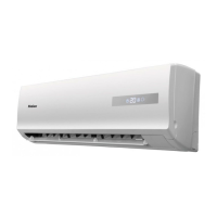
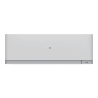
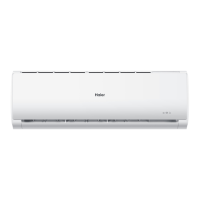
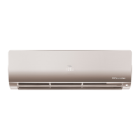
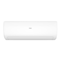
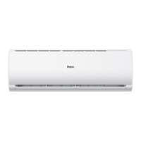
Lists and describes the main functional features of the air conditioner.
Provides electrical, capacity, and physical specifications of the unit.
Identifies the sensors used in the system and their purpose.
Illustrates the refrigerant flow in cooling and heating modes.
Details connectors on the PCB and lists PCB model information.
Describes how the system automatically selects cooling or heating modes.
Explains temperature control, fan speed, and airgate in cooling mode.
Details the operation and control features of the dehumidifying mode.
Explains temperature compensation and operation in heating mode.
Describes how to activate and use the strength operation mode.
Explains how to activate mute operation for heating and cooling.
Details the 24-hour on/off timing methods and settings.
Explains the 8-hour dormant operation, including temperature adjustments.
Describes the function of the urgency button for automatic and test operations.
Explains how the system prevents frosting during low load conditions.
Details the protection mechanism for high coil temperatures.
Describes malfunctions when indoor and outdoor operations conflict.
Outlines methods to confirm various sensor and communication abnormalities.
Explains how to enter and exit single indoor system operation.
Describes how the system stores status upon power interruption.
Details the steps and indicators for the test program.
Provides tables of resistance values for sensors at various temperatures.
Shows the external dimensions of the indoor unit in millimeters.
Indicates the center of gravity location on the unit.
Provides important warnings before starting diagnostic procedures.
Lists common operating problems and their corresponding checks and measures.
Lists error codes indicated by the indoor display and outdoor LED.
Details procedures for diagnosing thermistor and related abnormalities.
Explains how to diagnose and resolve EEPROM related errors.
Provides troubleshooting steps for indoor fan motor issues.
Details troubleshooting for outdoor DC fan motor faults.
Explains IPM protection and troubleshooting steps.
Details diagnosis and solutions for compressor over-current issues.
Outlines troubleshooting for communication faults between IPM and PCB.
Describes diagnosis for over/under voltage faults and related components.
Details troubleshooting for overheat protection related to discharge temperature.
Provides troubleshooting steps for communication failures between units.
Explains detection and troubleshooting for loss of synchronism.
Details diagnosis for high work-intense protection in heating mode.
Presents schematic diagrams of the electronic circuits.
Step-by-step guide to removing the front panel of the indoor unit.
Instructions for removing the main casing of the unit.
Details the process for removing the horizontal flap and stepper motor.
Guides the removal of the horizontal louver and the control box.
Step-by-step procedure for removing the heat exchanger.
Instructions for removing the fan rotor and fan motor.
| Cooling Capacity (Ton) | 1 Ton |
|---|---|
| Energy Efficiency Rating | 3 Star |
| Compressor Type | Rotary |
| Refrigerant | R32 |
| Power Supply | 220-240V, 50Hz |
| Power Consumption (Cooling) | 1050 W |
| Type | Inverter |
| Cooling Capacity | 12000 BTU/h |
| Air Flow Rate | 550 CFM |
| Air Flow (Indoor) | 550 CFM |