Do you have a question about the Haier AS25S2SF1FA-S and is the answer not in the manual?
Explains the meaning of each character in the model name for Haier air conditioners.
Details on checking embedded wire diameter and integrity before installation.
Important warnings and precautions to be observed during repair work.
Advises on using correct parts and tools after repair to ensure product safety and functionality.
Guidelines for post-repair inspection of electrical connections, grounding, and insulation resistance.
Explains the meaning of icons used in the manual (Note, Caution, Warning, Reference).
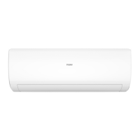
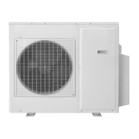
Outlines the primary functions and operational parameters of the air conditioning system.
Describes the automated mode where the system selects cooling or heating based on room temperature.
Details the operational parameters and features of the cooling mode, including temperature settings and fan speeds.
Explains the dehumidifying mode's temperature control range and operational features.
Covers the heating mode's temperature control, features, and fan speed adjustments.
Explains the 'strength operation' mode and how it interacts with other functions.
Details the 'mute operation' mode for reduced noise during heating or cooling.
Describes the 'air refreshing' function, noting it's not applicable to this model.
Explains the 24-hour on/off timing functions for controlling operation schedules.
Details the 'dormant operation' mode, specifying temperature adjustments over time.
Explains the 'urgency button' function for immediate operation, test, or malfunction display.
Describes the 'low load protection control' to prevent indoor heat exchanger frosting.
Details the 'high load protection control' to prevent overheating.
Explains how the system handles abnormal operations when indoor and outdoor systems conflict.
Describes the 'malfunction list resume' feature for displaying past errors.
Outlines methods for confirming various abnormalities like sensor failures or communication issues.
Explains how to operate a single indoor unit independently.
Details the 'power cut compensation' feature for retaining settings.
Describes the procedure for running a comprehensive test program.
Mentions a 'time cutting function' related to CPU speed.
Explains the function of the 'room card' for controlling the unit.
Provides cautions to be observed before starting the diagnostic process.
Lists common symptoms and the corresponding checks and measures for diagnosis.
Lists error codes displayed on the indoor panel and their corresponding fault descriptions.
Details abnormalities related to thermistors, including symptoms and troubleshooting steps.
Explains EEPROM errors, their causes, and troubleshooting steps.
Covers malfunctions of the indoor fan motor, detection methods, and checks.
Details faults in the outdoor DC fan motor, including detection and troubleshooting.
Explains IPM protection, its causes, and troubleshooting procedures.
Details over-current issues with the compressor, detection, and possible causes.
Describes communication faults between IPM and the outdoor PCB.
Covers faults related to over or under voltage in the power supply.
Details overheat protection for discharge temperature and its troubleshooting.
Explains communication faults between the indoor and outdoor units.
Addresses loss of synchronism detection in the inverter side current.
Covers high work-intense protection triggered by heat exchanger thermistor limits.
Provides the wiring diagram for the indoor unit of the air conditioner.
Specifies the type of air conditioning system covered by the removal procedure.
Specifies the type of air conditioning system covered by the removal procedure.
Step-by-step instructions for removing the front panel of the indoor unit.
Instructions for lifting and removing the control box cover.
Steps for removing the air filters from the unit.
Procedure for removing the main casing of the unit.
Steps for removing the horizontal flap and its associated stepper motor.
Instructions for removing the horizontal louver and the control box.
Procedure for removing the heat exchanger unit.
Steps for removing the fan rotor and its motor.