.10.
fig.1
fig.2
Installation
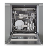
Positioning the Appliance
Position the appliance in the desired location. The back should
rest against the wall behind it, and the sides, along the adjacent
cabinets or wall. The dishwasher is equipped with water supply
and drain hoses that can be positioned to the right or the left to
facilitate proper installation.
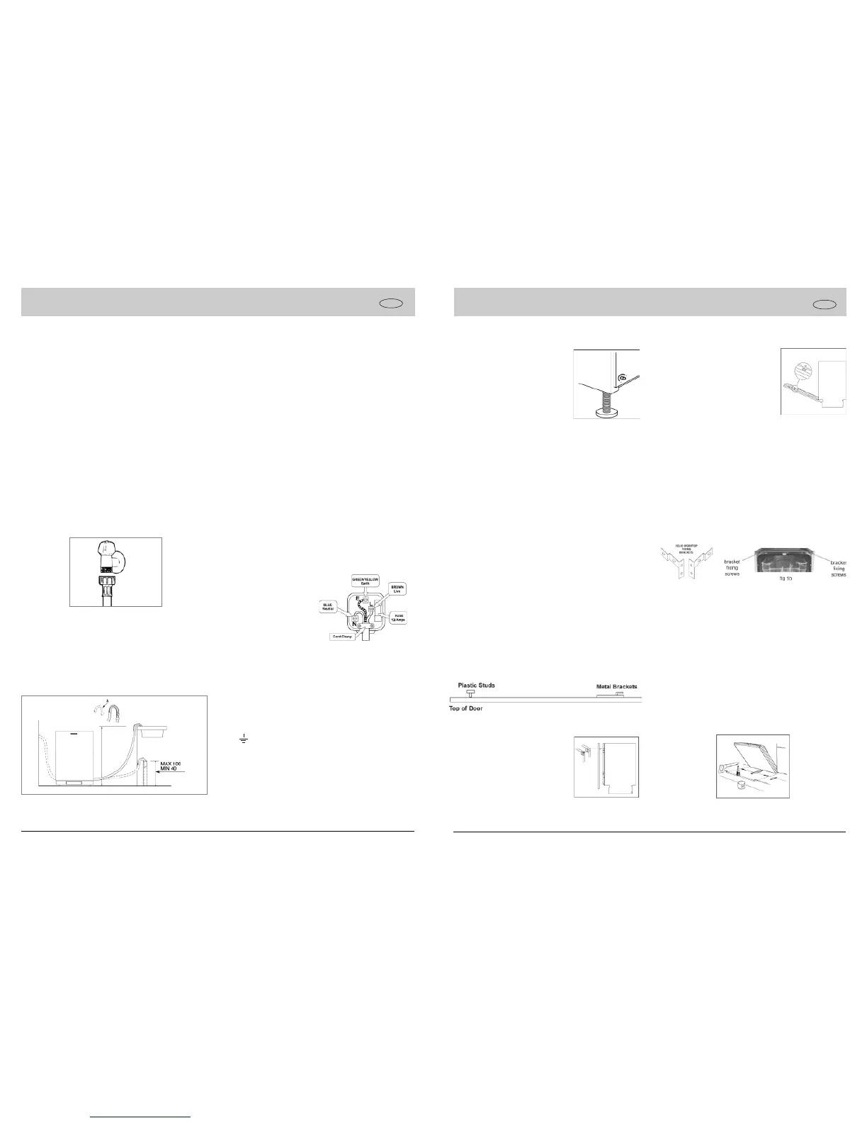
Levelling the Appliance
Once the appliance is positioned, adjust the feet (screw them in
or out) to adjust the dishwasher, making it level. In any case, the
appliance should not be inclined more than 2˚. If the appliance is
level, it will help ensure proper performance.
Cold Water Connection
Connect the cold water supply hose to a threaded 3/4(gas)
connector, inserting the small filter supplied with the dishwasher
and making sure that it is fastened tightly in place (see Fig.1).
If the water pipes are new or have not been used for an extended
period of time, let the water run to make sure that the water is
clear and free of impurities. If this precaution is not taken, there
is a risk that the water inlet can get blocked and damage the
appliance.
Drain Hose Connection
Insert the drain hose into a drain pipe with a minimum diameter
of 4cm, or let it run into the sink, making sure to avoid bending
or crimping it. Use the special plastic support that comes with
the appliance (see Fig.2). The free end of the hose must be at a
height between 40 and 100 cm and must not be immersed in
water.
Attention:
The special plastic hose support must be solidly fastened to the
wall to prevent the drain hose from moving and allowing water to
spill outside the drain.
ELECTRICAL CONNECTION (UK ONLY)
For your safety please read the following information.
Caution:
The dishwasher plug must be accessible even when the appliance is
installed as a built-in unit so that maintence can be done safety.
Warning: This appliance must be earthed.
The appliance must be connected to a 220-240 volts 50 cycle
AC supply by means of a three pin socket, suitably earthed and
should be protected by a 13 amp fuse in the plug or a 15 amp
fuse in the consumer unit.
The appliance is supplied with a moulded 13 amp 3 pin mains
plug fitted with a 13 amp fuse. Should the fuse require
replacement, it must be replaced with a fuse rated at 13 amp
and approved to BS1362.
The plug contains a removable fuse cover that must be refitted
when the fuse is replaced. In the event of the fuse cover being
lost or damaged, the plug must not be used until a replacement
cover has been obtained.
If the moulded mains plug is unsuitable for the socket outlet in
your home or is removed for any other reason, then the fuse
should be removed and the cut off plug disposed of safely to
prevent the hazard of electric shock.
There is a danger of electric shock if the cut off plug is inserted
into any 13 amp socket outlet.
How to wire a 13 amp plug.
Important
The wires in the mains lead on this appliance are coloured in
accordance with the following code:
Green and Yellow - Earth
Blue – Neutral
Brown – Live
As the colours may not correspond with the markings identifying
the terminals in your plug proceed as follows.
The green and yellow wire must be connected to the terminal in
the plug which is marked with the letter E or with the earth sym-
bol or coloured green and yellow.
The blue wire must be connected to the terminal marked N or
coloured black.
The brown wire must be connected to the terminal marked L or
coloured red.
GB
.11.
Supplied with the appliance is a plastic
(self adhesive) anticondensation strip,
this should be fixed to the underside of
your worktop along the front edge. The
adjustable feet of the appliance allow it
to be raised up to 870mm, if the space
between the floor and the underside of
the work surface is greater than 870mm,
Stage 1
Installation cont..
To prevent damage to the floor covering, the appliance must be
installed using the plastic skids provided.
Stage 2
Connect the water, drain and electrical supplies (230 - 240V,
50Hz, 13A). We recommend that the appliance is connected to
a cold water supply.
Measure the width of the decor door.Align the template on the
rear of the door with the top of the door level with the top of the
template, and the left hand edge of the door in line with the mea-
sured door width. Mark the four fixing poisitions. Repeat on the
right hand side. Remove the template, and drill pilot holes in the
door in all eight positions using a suitable drill (take care not to
drill through the door). Attach the upper plastic studs and lower
fixing brackets to the decor door as shown below.
Stage 3
Position the decor door onto the front of
the dishwasher by locating the brackets
into the two plastic studs mounted either
side on the top of the door. Lift the de-
cor door until the lower brackets locate
into the slots in the appliance door.
Stage 4
then the appliance should be positioned on suitable wooden spac-
ers which should always be fixed to the floor. Always use a spirit
level to make sure that the appliance is level left to right and
front to back.(If the appliance is installed on a carpet, ensure
there is clearance beneath the appliance). The four adjustable
feet should be adjusted to the correct height; the rear feet are
adjustable via studs at the front of the appliance (fig 1a).
fig 1a
Align the top of the decor door with adja-
cent cabinets. Gently open door whilst
supporting the decor door. Once in the
lowered position, secure the decor door
using the fixing screws provided as
shown in the diagram. Cover the screw
heads using the plastic caps provided.
Stage 5
The dishwasher should now be screwed to the underside of the
worktop, via the two fixing holes in the top trim.
For non-wooden worktops (e.g. marble) two brackets are pro-
vided to allow the appliance to be secured to the sides of the
adjacent cabinets. The should be secured to the appliance us-
ing the two screws at the top of the chassis (see fig 1b), ad-
justed to the correct width and then screwed to the adjacent sides
panels using suitable screws.
Stage 6
The door balance can be adusted via two screws accessed
through two holes in the top of the front frame. Adjust these until
the door just remains open under its own weight and is level
when open.
Stage 7
Cut clearance in the plinth to allow the door to open fully and
seal edges with a suitable varnish to prevent water ingress.
Stage 8
GB
 Loading...