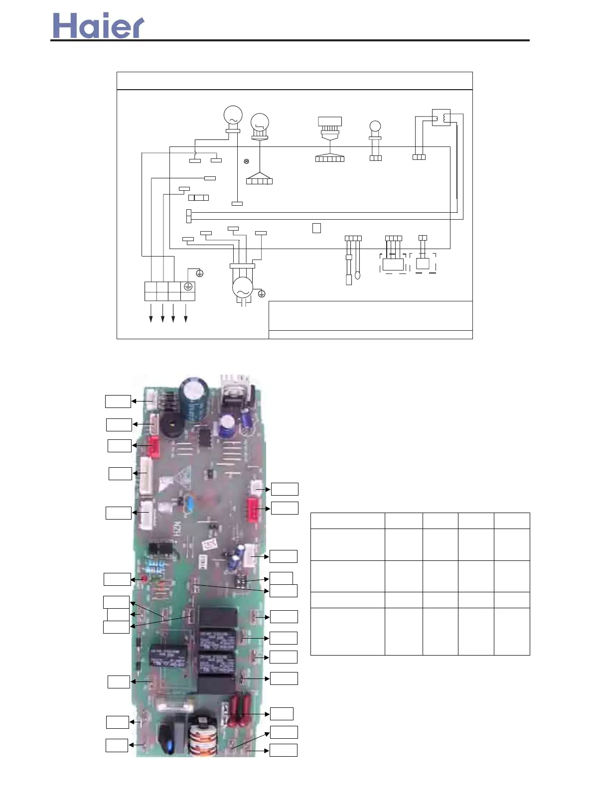
CIRCUIT DIAGRAM OF INDOOR UNIT
0150500673
FUSE
CN1
CN15
CN20
CN21
CN22
N2
CN4
LED3
CN3
N
CN2
L
7$9$&
CN16
CN17
N1
CN18
M
M
3803
6:,1*02725
1
Y/G
R
R
R Y BL W
B
B
W
W
Y
Y
32
Y/G
72287'22581,7
)$102725
M
&$3$&,725
<*
CN10
CN8
CN6
5(&(,9(5
FLOAT
SWITCH
DETECTOR
CN12
PIPING TEMP.
SENSOR
ROOM TEMP.
SENSOR
75$16)250(5
WIRED
CONTROLLER
CN14 CN13
ON
12
BM1
W:
WHITE
Bġ
BLACK
Rġ
RED
BLġBLUE Y:YELLOW Y/G:YELLOW/GREEN
NOTE:
1cTHE DETECTOR IS OPTIONAL,WHICH IS USED TO REALIZE REMOTE CONTROL FUNCTION.
2c
DASHED PARTS ARE SELECTED ACCORDING TO THE DIFFERENT MODELS.
3cTHE DIP-SWITCH HAS BEEN SETTED WHEN OUT OF FACTORY,PLEASE DO NOT CHANGE.
HBU-42CH03, HBU-42CI03, HBU-42HI03
CN12
CN10
CN11
CN8
CN6
CN16
LED3
CN3
CN1
CN9
CN2
CN23
CN25
CN13
CN14
BM1
CN24
CN22
CN21
CN20
CN17
CN4
CN18
CN15
0010452567 for HBU-42CH03, HBU-42CI03 and HBU-42HI03 indoor unit
Indoor dip-switch definition:
BM(2) BBMM(3) BM(4)
Cooling only /
heat pump
√/× * * *
Wired/remote
control
* √/× * *
Pre-set * * √/× *
With/without
temperature
compensation
* * * √/×
Notes: BM(3) and BM(4) are not available for
this models.
BM(1)
Wiring diagram and PCB photo
 Loading...