SERVICE MANUAL
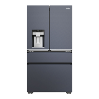
Model: HFD647AS/HB21TSSAA
3
4-9. Door-open warning·······················································································19
4-10. Energy saving display ··················································································19
4-11.Power off memory························································································19
4-12. Time adjustment and display ·······································································19
4-13. Ambient temperature display ·······································································19
5.
Control principle and related test functions·························································· 20
5-1. Air Damper······································································································ 20
5-2. Control principle of fan motor·········································································· 20
5-3. Defrost control principle ·················································································· 20
5-4. Ice- making process ························································································21
5-5. Self-testing Function 22
5-6. Ice-maker Inspection Mode 23
6. System flow principle······························································································· 24
6-1. System flow scenograph················································································· 24
6-2. System flow chart···························································································· 24
7. Circuit diagram·········································································································· 25
7-1. Main control PCB diagram ·············································································· 25
7-2. Brief principle diagram ···················································································· 27
7-3.Sensor and error code ····················································································· 28
7-4.
Display Error Codes Information ····································································· 28
8. Water line map ···········································································································29
8-1.Th e water line sketch map ···············································································29
8-2.Water line scenograph ·····················································································30
8-3.
Water inlet quantity setting (HFD647A*) 30
9. Trouble shooting ·······································································································31
9-1.Frequently problems·························································································31
 Loading...