3-3. L42K3
1. Lay down the unit so that back cover faces
upward
3. Remove the stand
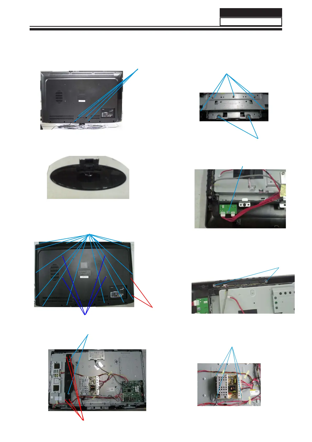
3-3-2. Remove the Back Cover
Remove the fifteen screws indicated (See
picture below.)
Service Manual
Model No.:
21
2. Remove the four screws indicated with
the blue lines in the picture above.
3-3-1. Remove the Stand
14 screws (ST4*12)
3-3-5. Remove the key board
4 Screws(M4*16)
2 screws (ST3*10)
2 Screws(ST4*16F)
3-3-4. Remove the connecting metal
board of base
5 Screws(M4*8)
2 Screws(ST4*12)
1 Screw(ST4*12)
3-3-3. Remove the speaker and bracket
3-3-6.Remove the remote board
2 Screws(ST3*10)
Remove the two screws indicated by the
blue lines in below picture.
3-3-7. Remove the power supply
Remove the three screws indicated by the
blue lines in below picture.
3 Screws(ST3*10)
4 screws(M6X16)
4 Screws(M4X8)

 Loading...