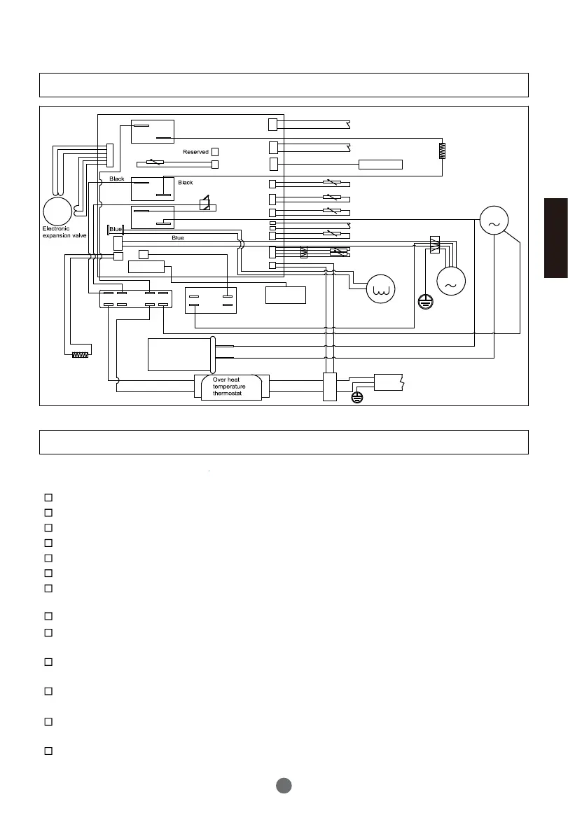
Wiring diagram
Commissioning
Installers shall use checking list for trial operation of water heaters as per the user manual
and make in .
√
□
Electrical wires are fixed securely?
Water drain pipes are connected correctly?
Ground wires are connected securely?
Supply voltage conforms to relevant electric codes?
The control panel works well?
All noises are normal?
The water tank has been connected with dedicated pressure relief valve (TP valve) and
check valve?
Materials for hot/cold water pipes conform to requirements of use of hot/cold water?
After the water system is completed, the water tank is filled with water? Is there water
drained out of the water outlet of the hot water pipeline?
After the water pipe of the water system is filled, check the whole water pipeline. There
is no leakage?
After the water system is filled with water, is there water flowing out after pressure is
relieved via the automatic safe pressure relief valve?
After the water system is filled with water and after leakage check, all outdoor water
pipelines are applied with heat insulation treatment?
The drain valve, drain pipe and pressure relief valve drain pipe of the water tank have
been connected to the sewage system and the drainage can be carried out well?
Installation introduction
English
23
R
C
S
Solar or boiler sensor( for HP250M3C )
K1
K3
K9
CN15
CN6
CN19
CN4
CN12
CN7
CN14
CN13
CN16
CN5
M
CT1
CN9
CN11
CN20
ECO1
ECO2
Municipal low power switching signal
CN3
CN1
M
Connector
CN18
CN17
M
CN25
Power cord
Leakage protection coil
Boiler switching signal (for HP250M3C)
Electrical heater
Compressor
Black
Blue
White
White
High pressure switch
Display panel
Ambient temperature sensor
Exhaust temperature sensor
Evaporator sensor
Tank temperature sensor
Four-way valve
Fan
Blue
Blue
Brown
Brown
Black
White
Compressor
capacitor
Brown
Black
Blue
Blue
Brown
Black
Heating strip
White
White
Blue
Blue
Lower electrical heater
Current transformer
Intake temperature sensor
Terminal block
Fan capacitor
Transformer