Connector Wiring Diagram
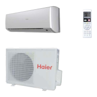
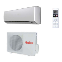
Domestic Air Conditioner
9
4.Printed Circuit Board Connector Wiring Diagram
4.1˖Indoor unit Connectors
Connectors
PCB(1) (Control PCB) For HSU-24HEG03/R2(DB)
1) CN9 Connector for fan motor
2) CN6 Connector for heat exchanger thermistor and Room temperature thermistor
3) CN5 Connector for UP&DOWN STEP motor
4) CN21 Connector for power N wire
5) CN22 Connector for power L
6) CN7 Connector for display board
7) CN23 Connector for communicate between the indoor board and the outdoor board
8) CN35 Connector for long-range control
Note: Other designations
PCB(1) (INdoor Control PCB)
1) SW1 Connector for Forced operation ON / OFF switch
2) SW2 1 Select remote code A or B,2 Select 25 or 35 ,3 Select room card able or disable
3) SW4 Select 20 or other,if select 20,SW2 must select 25(ON)
4) RV1 Varistor
5) FUSE1 Fuse 3.15A/250VAC
 Loading...