

A
Amanda SmithJul 31, 2025
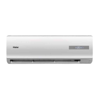
Why is my Haier HSU09VHJ Air Conditioner cooling poorly?
- MMatthew BurnettJul 31, 2025
Poor cooling in your Haier Air Conditioner can stem from several factors. Start by checking if the air filter is dirty and clean it if necessary (ideally every 15 days). Ensure there are no obstructions blocking the air inlet or outlet. Verify that the temperature is set correctly for your needs. Also, check for open doors or windows, direct sunlight entering the room (use curtains to block it), and excessive heat sources or a large number of people in the room.