4
The black terminal of the controller communication line is connected with the black
harness terminal at the lower outgoing line port of the unit� The other end of the controller
communication line is pressed on the wiring base of the controller, and the corresponding
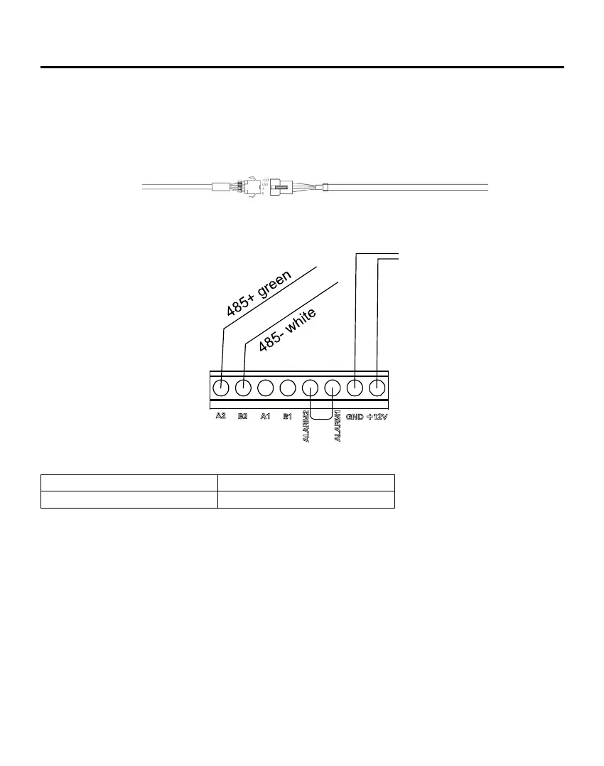
relationship is red~+12V, black~GND, green~A2 and white~B2�
Connection terminal between controller communication line and IDU:
The Split IDU
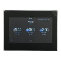
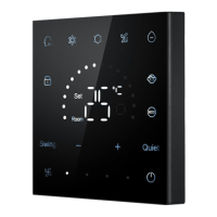
Controller
All of the power supply and communication 485 cables between each module and terminal
module to the controller are double core shielded twisted-pair cable. Specic wiring as the
table below:
Controller
12V- black
12V+ red
Controller Installation
The communication line is connected with the controller
The length of signal line Wiring dimension
≤100m 0�75mm
2
×4
Fix the screw through the bracket on the 86 cassettes and connect the connection� The red
connects to the +12V and black to GND, the green connects to A2, and the white connects
to B2. Please pay attention to the line order. Then the controller is xed down.
Notes:
1� B1 and A1 are unavailable�
2� B2 and A2 for 485 interface, access to split unit's 485 B and A, paying attention to line
order�
3� ARALM1 and ALARM2 factory default is connected, if not be connected, then the main
interface of the controller will display alarm information, and all indoor units will be turned o.
 Loading...