This document describes the HW-WA101DBT Split Controller, an operation and installation manual for a wired controller. It provides essential information for both setting up and using the device, including its physical components, wiring instructions, and configuration options.
Function Description
The HW-WA101DBT Split Controller is designed to manage split air conditioning systems. It acts as an interface for users to control and monitor the parameters of indoor units. The system supports both main and sub-controller configurations. A main controller has full control over unit parameters and operation status, while a sub-controller can only view unit parameters without the ability to change the operation status. This hierarchical control structure allows for flexible system management in various environments. The controller also features interfaces for power supply, communication with the indoor unit, fire alarm linkage, and third-party integration, enhancing its versatility and integration capabilities within a broader building management system.
Important Technical Specifications
- Model: HW-WA101DBT
- Power Supply: 12V DC. The manual emphasizes paying attention to the polarity ("+", "-") of the power supply.
- Communication Port (B2, A2): Used for connecting to a converter. The manual specifies A2 as 485+ and B2 as 485-.
- Third Party Interface (B1, A1): Reserved port, with A1 as 485+ and B1 as 485-. Note: B1 and A1 are unavailable for the Split Controller itself, while B2 and A2 are available.
- Fire Alarm Linkage Contact (ALARM1, ALARM2): Reserved port. Short-circuiting ALARM1 and ALARM2 triggers the fire alarm linkage. The factory default setting for ALARM1 and ALARM2 is connected; if not connected, the main interface will display alarm information, and all indoor units will be turned off.
- Communication Line: Double-core shielded twisted-pair cable for power supply and 485 communication.
- Maximum Signal Line Length: ≤100m.
- Wiring Dimension: 0.75mm²×4 for communication lines.
- Dimensions: 133mm (width) x 103mm (height) x 17mm (depth).
Usage Features
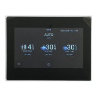
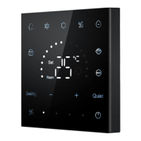
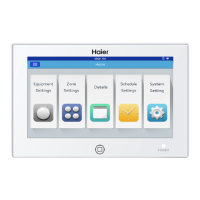
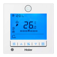
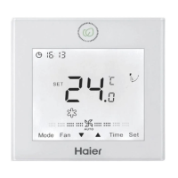
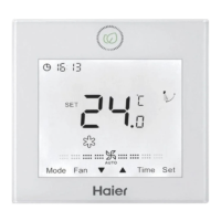
- Display / Touch Area: The primary interface for user interaction, allowing for parameter viewing and setting.
- Restart Buttons:
- Restart button ①: Located on the front, holding it for 10 seconds restarts the controller and checks software normalcy.
- Restart button ②: Located on the back, pressing it restarts the controller and checks the controller chip normalcy.
- Main/Sub Controller Setting: Users can configure the controller as either a main or sub-controller through the "SETTING → GENERAL" menu.
- MAIN: Allows full control and viewing of unit parameters.
- SUB: Allows only viewing of unit parameters, without control capabilities.
- Installation Settings: Accessible via "SETTING → INSTALLATION" with a password (841226). This interface is used for specific installation methods, detailed in the indoor unit's installation manual.
- Alarm Information: The controller displays alarm information on the main interface if the ALARM1 and ALARM2 contacts are not connected, leading to all indoor units being turned off.
Maintenance Features
- Software Restart: Restart button ① allows for a software restart, useful for troubleshooting software-related issues.
- Chip Restart: Restart button ② allows for a hardware restart, useful for troubleshooting chip-related issues.
- Installation Condition Guidelines: The manual provides crucial guidelines for installation to ensure proper operation and longevity:
- Avoid installation near devices producing electrical interference (e.g., AC motors, radio transmitters, network routers, consumer electronics, computers, auto-door openers, elevators).
- Do not install in wet locations.
- Avoid locations with violent shaking.
- Do not install in direct sunlight or near heat sources.
- Wiring Instructions: Detailed wiring diagrams and specifications are provided for connecting the controller to the indoor unit and power supply, ensuring correct installation and minimizing potential issues. The manual explicitly states the color-coding for wires (red~+12V, black~GND, green~A2, white~B2) and emphasizes paying attention to the line order.
- Mounting Control: Instructions for attaching the mounting plate to the wall, specifying the use of A/B holes for an 86mm box and C/D holes for a 120mm box, with an emphasis on the "UP" indicator for correct orientation.
- Documentation: The manual advises users to read it thoroughly before use and to keep it safely for future reference, aiding in ongoing maintenance and troubleshooting.