Do you have a question about the Haier SUPER MATCH AS20S2SF2FA and is the answer not in the manual?
Explains the components and meaning of the product model number.
Details general safety precautions for repair work and product operation.
Provides safety advice for after the repair work is completed.
Outlines the steps and checks required after the repair is done.
Explains the meaning and usage of icons within the service manual.
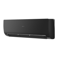
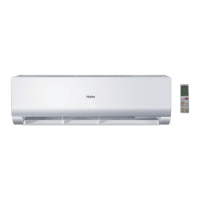
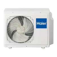
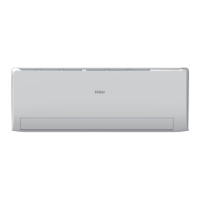
Lists and describes the main features of the air conditioning unit.
Details the electrical, performance, and physical specifications of the unit.
Lists the sensors used in the unit and their specific functions.
Illustrates the refrigerant piping for cooling and heating modes.
Details the connectors on the PCB for various internal components.
Overview of the unit's primary operational modes and control logic.
Describes how the system automatically selects operating modes based on conditions.
Details cooling mode settings, temperature control, and airflow adjustments.
Explains the settings and control features for the dehumidifying mode.
Details heating mode settings, temperature compensation, and fan control.
Describes the strength operation mode and its activation conditions.
Explains the mute operation mode for quieter performance.
Details the 24-hour timer functions for setting on/off operations.
Explains the automatic temperature adjustment feature during sleep.
Describes the urgency button function for testing and status checks.
Details the protection mechanism against frosting in low load conditions.
Explains the protection against overheating in high load conditions.
Describes malfunctions due to system mismatches and confirmation approaches.
Details single indoor system operation, power cut compensation, and room card functions.
Explains the procedure for executing the system's built-in test program.
Provides resistance values for room and pipe sensors at various temperatures.
Provides guidance for diagnosing and troubleshooting unit operational problems.
Lists warnings and conditions that trigger diagnostic procedures.
Lists common problems, check items, and measures to resolve them.
Lists error codes and their descriptions displayed on the indoor unit.
Details thermistor failures, causes, and troubleshooting steps.
Describes EEPROM errors, their causes, and potential solutions.
Explains indoor fan motor issues, detection methods, and checks.
Details outdoor fan motor faults, detection, and common causes.
Explains IPM protection faults, detection methods, and troubleshooting steps.
Describes compressor over-current faults and their potential causes.
Details communication faults between the IPM and the outdoor PCB.
Explains power supply over or under voltage faults and troubleshooting steps.
Describes overheat protection activation due to high discharge temperature.
Details communication faults between the indoor and outdoor units.
Details issues with inverter side current detection and loss of synchronism.
Explains high work-intense protection triggered by heat exchanger temperature.
Provides the detailed electrical wiring diagram for the indoor unit.
Presents comprehensive circuit diagrams for the unit's electronic components.
Outlines the step-by-step procedure for removing the front panel.
Details the steps for lifting and removing the control box cover.
Procedure for safely removing the unit's air filters.
Instructions for loosening screws and releasing hooks to remove the casing.
Procedure for removing the horizontal flap and the stepper motor.
Procedure for removing horizontal louvers and the main control box.
Steps for loosening hooks, screws, and lifting the heat exchanger.
Procedure for loosening screws and removing the fan motor cover.
Steps to lift and slide the fan motor and fan for removal.
| Brand | Haier |
|---|---|
| Model | SUPER MATCH AS20S2SF2FA |
| Category | Air Conditioner |
| Language | English |