Do you have a question about the Haier Super Match Series and is the answer not in the manual?
Lists various indoor and outdoor unit models available in the Super Match series.
Details key features like easy installation, vacuum & charging, and maintenance panel.
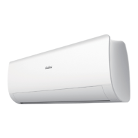
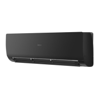
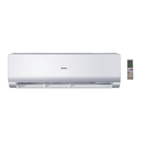
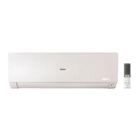
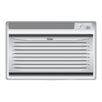
Highlights ease of installation and user-friendliness for indoor units.
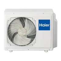
Discusses the wider operational range concerning outdoor temperature.
Describes the universal wireless controller and its user-friendly buttons.
Covers features, specifications, dimensions, diagrams, and installation for 4-way cassette units.
Details features, specifications, dimensions, diagrams, and maintenance for duct indoor units.
Provides detailed specifications for outdoor units including capacity, power, and refrigerant.
Shows dimensional drawings for outdoor units.
Illustrates wiring diagrams for outdoor units, including connections to indoor units.
Details the refrigerant piping diagrams for cooling and heating modes.
Lists standard and maximum values for piping length and height differences.
Presents sound pressure level data for various operating modes and speeds.
Provides detailed installation procedures and safety precautions for outdoor units.
Shows PCB diagrams and component layouts for indoor units.
Explains the settings and functions of indoor unit dip switches.
Details outdoor unit PCB components, dip switch settings, and functions.
Lists malfunction codes, their descriptions, and reference pages for diagnosis.
Provides troubleshooting guides for common operational issues and malfunctions.
Explains the functions and operations of the wired controller (YR-HD).
| Brand | Haier |
|---|---|
| Model | Super Match Series |
| Category | Air Conditioner |
| Language | English |