www.haiwell.com A Series Card-type PLC - Digital Module User Manual
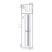
PWR:power indicator .green,constant light -Power normal; Not light - Power abnormal.
LINK:multi-status indicator, three colors (Red/ Yellow/ Green), as follow:
Reference processing mode
No communication of module
MPU has identified the module but no
communication
Serial or parallel port in communication
Green jitter: indicator on 30ms and off 30ms
Parallel power supply not enough,
must connect to external power supply
Without serial or parallel port in communication
Yellow flicker: indicator on 0.5s and off 0.5s
With serial or parallel port in communication
Yellow is darkened and jitter alternately: indicator
off 0.5s and jitter 0.5s
Firmware upgrade failed, reupgrade
the module firmware
Without serial or parallel port in communication
Red flicker: indicator on 0.5s and off 0.5s
With serial or parallel port in communication
Red is darkened and jitter alternately: indicator off
0.5s and jitter 0.5s
Hardware failure and maintenance
Without serial or parallel port in communication
With serial or parallel port in communication
Red jitter quickly: indicator on 30ms and off 30ms
3. Power Supply Specification
24V Output voltage (for input
and expansion
DC input power polarity reverse, over voltage protection
4. Environmental Specifications for Product
Environment Specification
Operating temperature:0~+55℃ Storage temperature:-25~+70℃ Humidity: 5~95%RH, No condensation
10~57 HZ, amplitude=0.075mm, 57HZ~150HZ acceleration=1G, 10 times each for X-axis, Y-axis and Z-axis
15G, duration=11ms, 6 times each for X-axis, Y-axis and Z-axis
DC EFT:±2500V Surge:±1000V
1500VAC/1min between AC terminal and PE terminal, 500VAC/1min between DC terminal and PE terminal
Between AC terminal and PE terminal @500VDC,>=5MΩ ,all input/output points to PE terminal @500VDC
Avoid dust, moisture, corrosion, electric shock and external shocks
5. Digital Input (DI) Specification
Environment Specification
No voltage contact or NPN/PNP
6.4ms DEFAULT, can be configured to 0.8~51.2ms
Independent optoelectronic isolation for each channel
LED's lighting indicates ON, no light indicates OFF
MPU internal power supply:DC power supply (SINK or SOURCE) 5.3mA@24VDC
6. Digital Output (DO) Specification
NPN or PNP transistor output-T/P
2A/1 point, 8A/4 points COM
0.5A/1 point, 2A/4 points COM
 Loading...