Français
Deutsch
English
Attaching the temperature knob
1) Hold the grip firmly and insert the lock key into the keyhole.
2) Turn the temperature knob in a clockwise direction and set the temperature to
maximum value (540℃) with the lock key.
3) Attach the temperature knob to the iron and
match the arrow of the knob with the
maximum value (540℃).
4) Using a crosspoint screwdriver, secure the
small screw in the center of the knob to the
iron.
■ How to use the lock key
This product is shipped with the temperature knob attached.
After the temperature knob is removed, the set temperature cannot be easily
changed unless the lock key is used.
Removing the temperature knob.
1) Turn the temperature knob in a counterclockwise direction and set the
temperature to minimum value (240℃).
2) Remove the screw in the center of the temperature
knob with a crosspoint screwdriver to remove
the temperature knob.
Set the temperature by lock key
1) Hold the grip firmly and insert
the lock key into the keyhole.
2) Turn the key while pressing it
in firmly.
3. WARNINGS, CAUTIONS, NOTES AND EXAMPLES
4. OPERATION
7. TROUBLE SHOOTING GUIDE
●
To prevent accidents or damage to the HAKKO FX-601, be sure to observe the following:
CAUTION
● Do not use the unit for applications other than those specifically described in the
instruction manual.
● Do not strike the iron against hard objects to remove excess solder. This will
damage the iron.
● Do not modify the HAKKO FX-601.
● Use only genuine Hakko replacement parts.
● Do not allow the HAKKO FX-601 to become wet, or use it with wet hands.
● Hold the power plug when plugging it in and unplugging it.
● Be sure the work area is well ventilated. Soldering produces smoke.
● The unit is for a counter or workbench use only.
● Do not perform any other actions that may be considered dangerous.
WARNING
6. MAINTENANCE
Iron does not heat up.
Iron is sometimes hot and sometimes cold.
Iron does not reach setting temperature.
Solder does not wet to the tip.
Value of the tip to ground potential and tip to
ground resistance is too high.
■ Temperature Calibration
To adjust the tip temperature to the set temperature at higher accuracy, calibrate
the temperature. When changing the set temperature or replacing tips and heating
elements, be sure to calibrate the temperature. The temperature is initially set to
410˚C±10˚C.
Adjust to the desired temperature setting by measuring the tip temperature using a
tip thermometer (optional accessory) and turning the CAL knob with a crosspoint
screwdriver.
■ Cleaning the grounding line.
When the tip to ground resistance and tip to ground potential is out of normal value
due to degradation by use, remove the oxides from the sections indicated in the
figure below using sandpaper.
Clean the grounding line periodically.
■ Procedure
1) Turn the temperature knob to set the temperature.
2) When the power plug is plugged in, the LED lamp will light.
* While the LED lamp is lit (temperature is increasing), it is recommended to use
an iron holder.
3) When the iron temperature reaches the set temperature, the LED lamp will
change from lit to blinking.
Caution
If turning the temperature knob without pressing it fully, the lock key may be
broken.
When power is ON, tip temperatures will be between 240℃ and 540℃. (460℉ to 1000℉)
To avoid injury or damage to personnel and items in the work area, observe the following:
●This appliance can be used by children aged
from 8 years and above and persons with
reduced physical, sensory or mental capabilities
or lack of experience and knowledge if they
have been given supervision or instruction
concerning use of the appliance in safe way
and understand the hazards involved.Children
shall not play with the appliance.
Cleaning and user maintenance shall not be
made by children without supervision.
●Place the handpiece on the iron holder
when it is not in use.
●If the power cord is damaged, it must be
replaced by the manufacturer, its service
agent or similarly qualified person in order to
avoid personal injury or damage to the unit.
● Do not touch the tip or the metal parts near the tip.
● Do not allow the tip to come close to, or touch, flammable materials.
● Inform others in the area that the unit is hot and should not be touched.
● Turn the power off when not in use, or left unattended.
● Turn the power off when changing parts or storing the HAKKO FX-601.
WARNING
Since this product becomes very hot, use extra caution during use. Except the case
especially indicated, always turn the power switch OFF and disconnect the power plug
before performing any maintenance procedure.
Power Consumption
Temperature Stability
Temperature Range
100V-47W/110V-56W/
120V-67W/220V-42W/
230V-46W/240V-50W
±1 ℃
at idle temperature
240 - 540℃
Tip to Ground
Resistance
Weight (w/o cord)
Total Length (w/o cord)
Heating Element
Tip to Ground Potential
< 2 Ω
6
8
g
w
i
t
h
T
1
9
-
D
6
5
t
i
p
2
3
7
m
m
w
i
t
h
T
1
9
-
D
6
5
t
i
p
Ceramic
< 2 mV
2. SPECIFICATIONS
Specifications and appearance are subject to change without notice.
Symptoms
Cause
Treatment
Iron is not properly connected to power source.
Heating element failure
Short in cord
Heating element is NOT properly soldered.
Improper CAL adjustment
Tip is worn.
Tip setting temperature is too high.
Tip is worn.
Grounding line has not been cleaned properly.
Nut is not fastened tightly enough.
Connect properly.
Replace heating element.
Replace cord.
Solder heating element once again.
Recalibrate temperature.
Replace tip and then recalibrate temperature.
Reduce setting temperature.
Replace tip.
Clean grounding line.
Refasten.
5. TEMPERATURE SETTING
■ How to use the temperature knob
Hold the grip firmly and align the arrow mark of the temperature knob with the
desired temperature setting.
Since you can feel a click at each temperature, it is
easy to set the temperature.
* Temperature is also controlled in positions
between clicks.
–
6
0
1
4
6
0
C
A
L
4
1
0
3
6
0
3
1
0
5
4
0
2
4
0
Arrow mark
End of the pipe
Surface
240
310
360
410
460
540
Lock key*
Beaded cable tie
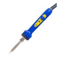
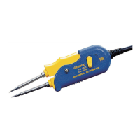
HAKKO FX-601
Temperature knob
CAL
LED lamp
1. PACKING LIST AND PART NAMES
Please make sure that all items listed below are included in the package.
HAKKO FX-601 soldering iron ..............1
Lock key ...............................................1
Beaded cable tie....................................1
Instruction manual ................................1
*Refer to “5. TEMPERATURE SETTING” when using the lock key.
–
6
0
1
4
6
0
C
A
L
4
1
0
3
6
0
3
1
0
5
4
0
2
4
0
–
6
0
1
4
6
0
C
A
L
4
1
0
3
6
0
3
1
0
5
4
0
2
4
0
–
6
0
1
4
6
0
C
A
L
4
1
0
3
6
0
3
1
0
5
4
0
2
4
0
–
6
0
1
4
6
0
C
AL
4
1
0
3
6
0
3
1
0
5
4
0
2
4
0
–
6
0
1
4
6
0
C
AL
4
1
0
3
6
0
3
1
0
5
4
0
2
4
0
–
6
0
1
4
6
0
C
AL
4
1
0
3
6
0
3
1
0
5
4
0
2
4
0
Insert
the lock key fully.
Insert
the lock key fully.
0
6
0
4
1
0
4
6
0
5
4
0
2
4
0
1 2
FX-601_EN_CaFR_DE_MAC_20210604.indd 2 2021/06/04 14:07