49
ESP Primer System Instruction Guide
p/n: 029-0810-01-0
Troubleshooting
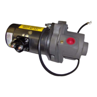
Primer Solenoid - 12VDC and 24VDC
Switch is dead - no
click is heard.
See electrical installa-
tion detail plate draw-
ing on page 54.
For 12VDC Solenoid,
see Figure 6-2:
“12VDC Solenoid
Arrangement Trou-
bleshooting” on page
50.
For 24VDC solenoid,
see Figure 6-3:
“24VDC Solenoid
Arrangement Trou-
bleshooting” on page
50.
Bad base ground. (For
24VDC - bad ground at
(
I ) terminal.)
Low voltage on switch
terminal. (For 24VDC -
bad voltage at (
S )
terminal.)
Dead switch wire.
Bad Battery.
Hardware not properly
tightened.
Check plastic body for
cracks allowing mois-
ture to enter.
• Check solenoid base screws for tightness and corrosion, especially
under the hold-down tangs - clean accordingly. Switch base must
be properly grounded to motor and motor to chassis.
• Continuity test and check each cable for defects, i.e., fraying,
splits, corrosion, etc. See electrical installation detail plate drawing
on page 54. Repair and/or replace accordingly.
• Check apparatus battery for full charge - service accordingly.
• Using VOM (volt ohm meter), check wires for proper voltage -
12VDC requires minimum of 9.0VDC; 24VDC requires minimum
of 18.0VDC.
• Check that hardware is tight and torqued to specifications. See
mechanical installation detail plate drawing on page 54.
• Hair line cracks in the plastic body allow moisture to enter and
short the internal circuity. If suspect, replace solenoid.
Switch chatters,
pops or clicks, but
the motor does not
work.
Chart continued on
next page.
Bad base ground. (For
24VDC - bad ground at
(
I ) terminal.)
Bad positive (+) or neg-
ative (-) cables.
Bad or weak battery.
Low voltage to switch
terminal. (For 24VDC -
bad voltage at (
S )
terminal.)
Hardware not properly
tightened.
Check plastic body for
cracks allowing mois-
ture to enter.
• Check solenoid base screws for tightness and corrosion, especially
under the hold-down tangs - clean accordingly.
• Continuity test and check each cable for defects, i.e., fraying,
splits, corrosion, etc. See electrical installation detail plate draw-
ing on page 54. Repair and/or replace accordingly.
• Check that each cable is tight and torqued to specifications. See
mechanical installation detail plate drawing on page 54.
• Check apparatus battery for full charge - service accordingly.
• Using VOM (volt ohm meter), check wires for proper voltage -
12VDC requires minimum of 9.0VDC; 24VDC requires minimum
of 18.0VDC.
• Check that hardware is tight and torqued to specifications. See
mechanical installation detail plate drawing on page 54.
• Hair line cracks in the plastic body allow moisture to enter and
short the internal circuity. If suspect, replace solenoid.
Condition
Possible
Cause
Suggested Corrective Action
Figure 6-1: Troubleshooting Chart