43
ESP Primer System Instruction Guide
p/n: 029-0810-01-0
Maintenance ❑
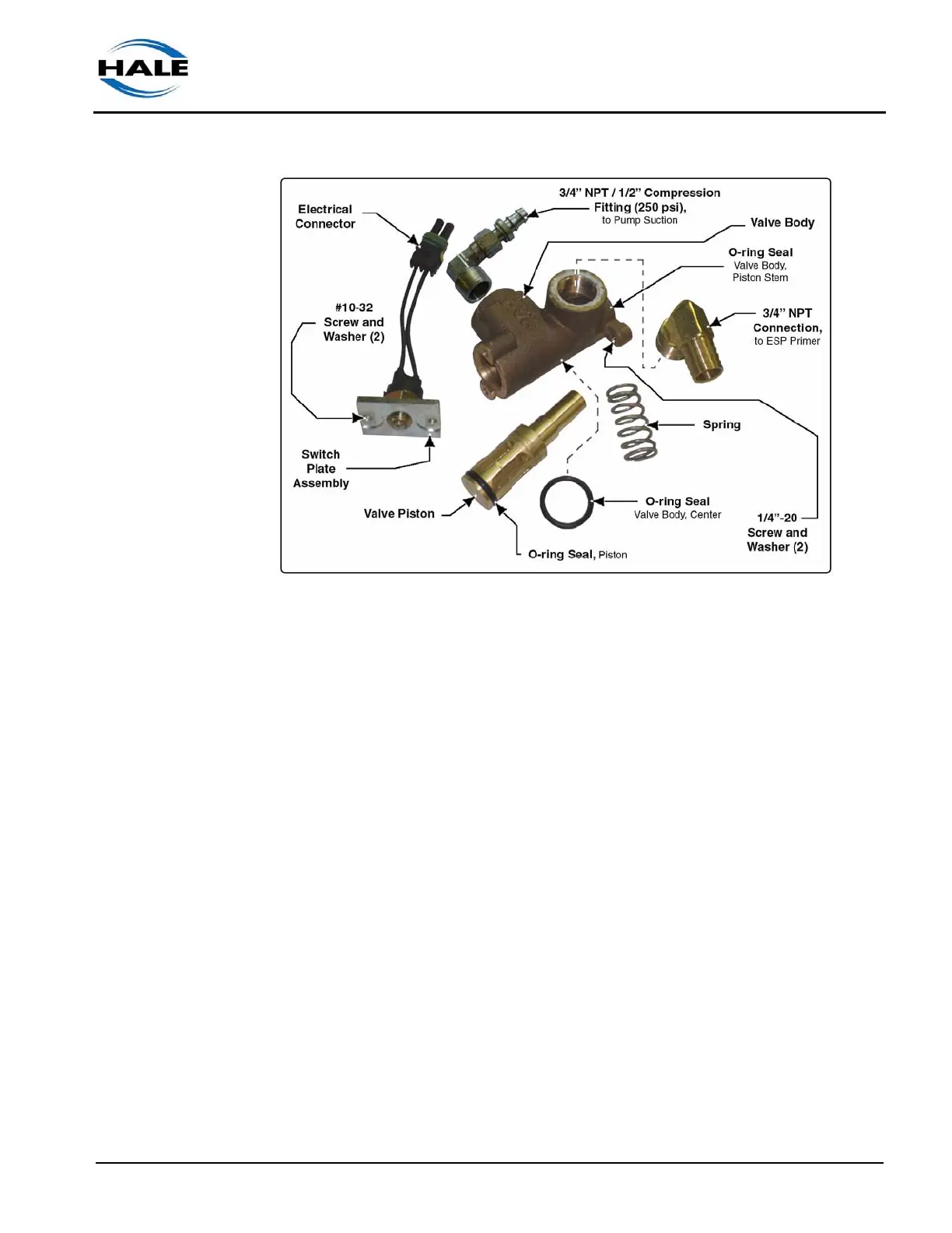
Figure 5-5: PVG Valve Parts Breakdown
3. Drain the pump in accordance with your departmental procedures. Have
clean disposable shop rags and oil dry handy.
4. Disconnect the ESP and pump vacuum hoses from the hose connections
on the valve body.
5. Remove both 3/4” fittings in the valve body to allow visible access to the pis-
ton and spring.
Insert a screw driver into the cage opening, through the pump port, to hold
the piston from spining as you remove (unscrew) the handle. DO NOT
attempt to secure the brass stem of the piston with vise grips. If the piston
stem is nicked or scratched it will damage the O-ring seal and cause leaks.
6. Remove the PVG valve handle from the valve setscrew stem. (See Figure
5-4: “Hale PVG Parts Overview” on page 42.)
7. Remove the two 1/4”-20 screws securing the valve and placard to the oper-
ator’s panel and remove the assembly from the apparatus.
8. Stabilize the unit (in a vise) and remove the two #10-32 screws and washers
from the switch plate. (See Figure 5-5: “PVG Valve Parts Breakdown.”)
9. Remove the switch plate with electrical connector and set safely aside.