EasyManua.ls Logo

HALE FoamLogix 3.3 - User Manual

HALE FoamLogix 3.3
122 pages
Print Icon
To Next Page IconTo Next Page
Loading...
6/26/2003
HALE PRODUCTS, INC. l A Unit of IDEX Corporation l 700 Spring Mill Avenue l Conshohocken, PA 19428 l TEL: 610-825-6300 l FAX: 610-825-6440
MANUAL P/N 029-0020-68-0, REV B, © 2003 HALE PRODUCTS, INC., PRINTED IN U.S.A.
ONOCEVERMORFDEGNAHCYBETADDVPA
731-30A GNITNIRPROFDESAELERWRP3002/20/5LAM
512-30B DETADPUWRP3002/03/6LAM
Hale Products cannot assume responsibility for product failure resulting from improper
maintenance or operation. Hale Products is responsible only to the limits stated in the product
warranty. Product specifications contained in this material are subject to change without notice.
All Hale products are quality components: ruggedly designed, accurately machined, precision inspected, carefully assembled
and thoroughly tested. In order to maintain the high quality of your unit, and to keep it in a ready condition, it is important to
follow the instructions on care and operation. Proper use and good preventive maintenance will lengthen the life of your unit.
ALWAYS INCLUDE THE UNIT SERIAL NUMBER IN CORRESPONDENCE.
DESCRIPTION, INSTALLATION AND
OPERATION MANUAL
MODEL 3.3 AND 5.0 ROTARY GEAR
PUMP ELECTRONIC FOAM
PROPORTIONING SYSTEM
Hale FoamLogix System Serial Number: _____________________________
Date Unit Placed in Service: _______________________________________
Fire Department: ________________________________________________
Engine Number: ________________________________________________
Calibration Factors:
Water Flow Factor:__________________________________________
Class A Foam Factor:________________________________________
Class B Foam Factor: _______________________________________
NOTICE: This manual is divided into four sections for clarity and ease of use. Section I: DESCRIPTION; Provides an
introduction to the Hale foam proportioning system along with guidelines for designing and ordering a complete
system. Section II: INSTALLATION; Provides information to assist the OEM with installation and initial set-up of Hale foam
proportioning systems on an apparatus. Section III: SET-UP AND CALIBRATION; Is used by the installer and end user for
start-up and calibration of the Hale foam proportioning system. Section IV: OPERATION; Is primarily used by the
apparatus user for proper operation and maintenance of the Hale foam proportioning system. Each manual section
can be a stand alone section or can be used in conjunction with each other.
FoamLogix
TM
Question and Answer IconNeed help?

Do you have a question about the HALE FoamLogix 3.3 and is the answer not in the manual?

Overview

The Hale FoamLogix system is a sophisticated electronic foam proportioning system designed for fire suppression applications. It accurately delivers foam concentrate at specified percentages (0.1% to 10.0%) directly into the water discharge stream, ensuring consistent foam solution regardless of changes in system pressure or the number of discharges in use. This system is engineered to prevent contamination of the booster tank, fire pump, and relief valve with foam concentrate when properly configured and installed.

Function Description:

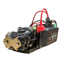
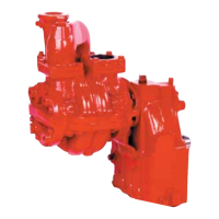
The core of the FoamLogix system is an electric motor-driven rotary gear pump, constructed from bronze and stainless steel for compatibility with a wide range of foam concentrates. The pump is close-coupled to the electric motor, eliminating the need for an oil-filled gearbox and reducing maintenance. An internal stainless steel relief valve protects the foam pump and discharge hoses from overpressurization.

A control unit, typically mounted on the operator panel, serves as the single control point for the system. It features a super bright digital LED display that shows water flow rate, total water flowed, foam concentrate injection percentage, and total foam concentrate used, depending on the selected display mode. A bargraph on the control unit indicates the approximate system capacity being utilized. Foam concentrate injection rates can be adjusted using dedicated buttons on the control unit.

The system operates based on constant monitoring of water flow by a flowsensor in the discharge piping and foam concentrate flow by a feedback sensor in the foam pump body. A computer chip in the control unit continuously compares these flow rates and adjusts the motor speed to maintain the operator-selected injection rate.

The FoamLogix system can be configured for single or dual foam concentrate tanks. Optional components include:

  • Air Dual Tank (ADT) valve: An air-operated foam tank selector that provides selection of foam concentrate based on operational demands. It includes an electrical interlock for low tank level sensors and concentrate injection rate.
  • Manual Dual Tank (MDT II) selector valve: A panel-mounted, manually operated selector for dual tank systems, also providing electrical interlock for low tank level sensors and concentrate injection rate. It is not suitable for top-mount operator panels due to gravity feed requirements.
  • Manual Single Tank (MST) selector: For single tank systems, providing a flush function connection to the electronic controls.
  • Strainers: Available in in-line strainer/valve assemblies (composite nonmetallic housing with stainless steel mesh) or panel-mounted FS series strainers (500 PSIG pressure rating). These protect the foam pump from debris.
  • Low Tank Level Sensors: Available in side mount, bottom mount, or top mount assemblies to protect the foam proportioner from dry running.
  • Check Valve Manifolds: Include flowsensor, check valve/injector fitting, and single or dual waterway check valve flappers.
  • Remote Activation Switch: Allows activation from the driver compartment or other remote locations.

Important Technical Specifications:

  • Foam Pump Output: Model 3.3 delivers 3.3 GPM (12 LPM), Model 5.0 delivers 5.0 GPM (19 LPM).
  • Maximum System Operating Pressure: Model 3.3 is 400 PSI (28 BAR), Model 5.0 is 250 PSI (17 BAR).
  • Maximum Operating Temperature: 160°F (71°C).
  • Pump Motor: ¾ HP (0.5 kW), available in 12 VDC (standard) or 24 VDC (optional).
  • Operating Ampere Draw: 30 AMPS @ 12 VDC (15 AMPS @ 24 VDC).
  • Maximum Ampere Draw: 60 AMPS @ 12 VDC (30 AMPS @ 24 VDC).
  • Electrical System: Designed for negative ground direct current electrical systems only.
  • Power Supply: Requires minimum 60 AMP electrical service (Model 3.3 and 5.0). Primary power should be supplied directly from the main apparatus battery or battery master disconnect switch/solenoids.
  • Hose Requirements:
    • Foam concentrate suction hose (not subject to flushing water pressure): Rated for 23 in (584.2 mm) Hg vacuum and 50 PSI (3 BAR) or greater. Clear hose is required to observe foam flow.
    • Foam concentrate suction hose (subject to flushing water pressure): Rated for 23 in (584.2 mm) Hg vacuum and maximum fire pump discharge pressure (500 PSI / 34 BAR minimum).
    • Foam concentrate discharge hose: ½ inch (13 mm) minimum ID, rated at 500 PSI (34 BAR) working pressure.
    • Foam concentrate bypass hose: ½ inch (13 mm) minimum ID, lower pressure rating acceptable as it does not see high operating pressures.
    • Flushing water hose: ½ inch (12 mm) minimum ID, capable of withstanding maximum fire pump discharge pressure (500 PSI / 34 BAR minimum).
  • Check Valves: Required in foam concentrate injection line (integral to injector fitting) and all water piping locations where foam concentrate could drain back into pumps or other components. Waterway check valves must be rated for 500 PSIG (34 BAR).
  • Flowsensor Installation: Requires a minimum of 6 times the pipe diameter of straight run pipe without fittings prior to the paddlewheel to reduce turbulence and ensure accurate readings.

Usage Features:

  • Control Unit Display: Provides real-time information on water flow, total water flowed, foam percentage, and total foam used. A bargraph indicates pump capacity in use.
  • Injection Rate Adjustment: Easily adjusted via buttons on the control unit.
  • Simulated Flow Mode: Allows operation of the foam pump without discharging water, useful for draining tanks, checking calibration, or manual foam injection if the flowsensor malfunctions.
  • Low Foam Tank Level Warning: The system interlocks with tank level switches, displaying "Lo A" or "Lo b" when a tank is low. If concentrate is not restored, the pump stops after one minute, displaying "no A" or "no b".
  • Priming Error Warning: "noPri" displayed if no foam concentrate flow is detected after 30 seconds of pump operation.
  • High Temperature/Low Battery Warning: "hiGh" for excessive ambient temperature, "Lo SP" for low power supply voltage.
  • Flushing Capability: ADT, MDT II, and MST selectors provide integrated flushing functions to clean the system after use, especially with Class B foams.
  • Password Protection: Calibration and default value settings are protected by passwords to prevent unauthorized changes.

Maintenance Features:

  • Regular Inspections: After each use, inspect hoses, wiring, flowsensors, and connections for tightness, corrosion, leaks, and damage.
  • Strainer Cleaning: After each use, remove and clean the foam strainer screen(s).
  • Calibration Verification: Monthly verification of water flow and foam feedback calibration is recommended.
  • Modular Design: The system uses modular components to simplify troubleshooting and repair. Electronic components are replaced as units, and opening them voids the warranty.
  • Grounding: Proper grounding with a flat braided ground strap is crucial to limit RFI/EMI interference.
  • Cable Management: Shielded cables are provided and should not be shortened or lengthened. Excess cable should be bundled flat, not coiled, to avoid acting as an antenna.
  • Relief Valve: Factory tested and set; typically does not require field adjustment.
  • Clear Suction Hose: Allows visual verification of foam concentrate flow.

HALE FoamLogix 3.3 Specifications

General IconGeneral
BrandHALE
ModelFoamLogix 3.3
CategoryWater Pump
LanguageEnglish

Related product manuals