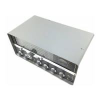
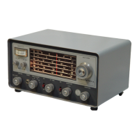
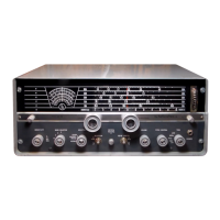
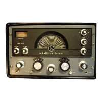
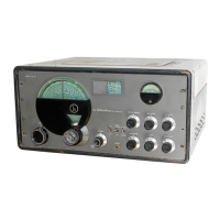
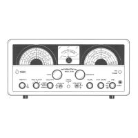
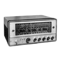
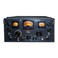
Do you have a question about the Hallicrafters SX-100 and is the answer not in the manual?
Inspect receiver for damage after unpacking and check shipping labels for instructions.
Place receiver in a well-ventilated area, avoiding warm locations for optimal performance.
Details on connecting single-wire and half-wave doublet antennas for optimal reception.
Instructions for connecting the receiver to AC power or an external DC power source.
Guidance on connecting external speakers, including impedance matching.
Information on headphone jack usage and compatible headphone impedances.
Adjusts RF and IF amplifier gain for optimal signal reception strength.
Selects appropriate coils and capacitors for desired frequency ranges.
Compensates for antenna loading effects to peak RF stage performance.
Selects reception mode for AM, CW, or SSB signals, affecting BFO and AVC.
Varies receiver selectivity to filter adjacent signals and reduce noise.
Eliminates or reduces interfering heterodyne or CW signals by suppressing narrow frequency bands.
Controls for wide and fine tuning of desired signals, including logging procedures.
Step-by-step guide for setting controls and tuning for AM broadcast reception.
Procedures for operating the receiver for Morse code (CW) reception.
Guide to receiving single-sideband (SSB) signals, including sideband selection.
Instructions on using the crystal calibrator to check and adjust dial accuracy.
Explains the function of the "S" meter for tuning and signal strength indication.
Lists the necessary equipment for performing receiver alignment procedures.
Specifies the starting positions for various controls before alignment.
Detailed step-by-step instructions for aligning different sections of the receiver.
Procedures for aligning the radio frequency stages across various bands.
Steps for calibrating the "S" meter for accurate signal strength readings.
Provides key technical data, including tubes, power, frequencies, and dimensions.
Explains the circuit design and function of the 50.5 KC Intermediate Frequency system.
Instructions on how to safely remove the chassis from the receiver cabinet.
Guidance on accessing and replacing vacuum tubes and dial lamps.
Details on how to perform mechanical and electrical adjustments for the "S" meter.
Step-by-step instructions for restringing the dial cable for tuning mechanisms.
| Type | Communications Receiver |
|---|---|
| Modes | AM, CW, SSB |
| Tubes | 12 |
| IF Frequencies | 455 kHz |
| Audio Output | 2.5 W |
| Power Supply | 117 V AC |
