Do you have a question about the Hallicrafters SX-110 and is the answer not in the manual?
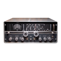
Details the Hallicrafters SX-110's precision build, sensitivity, and frequency coverage for AM/CW signals.
Instructions for checking the receiver for damage upon arrival and verifying shipping contents.
Guidance on selecting an appropriate location, avoiding heat and ensuring ventilation for the receiver.
Specifies the receiver's AC power requirements and warns about potential damage from incorrect sources.
Details on connecting single-wire and half-wave doublet antennas for optimal reception.
Describes the use and setup of a simple single-wire antenna for general reception.
Recommends a half-wave doublet for superior shortwave performance, detailing its installation.
Instructions for connecting external speakers to the designated terminals on the receiver.
Information on using the headphone jack, including automatic speaker disabling and headphone types.
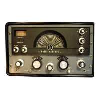
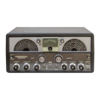
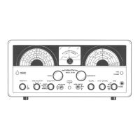
Introduces the receiver's controls and emphasizes gaining familiarity for full appreciation.
Explains the Sensitivity control's function in regulating output and enabling Automatic Volume Control (AVC).
Instructions on setting the Band Selector to choose the desired frequency band for tuning.
Guidance on adjusting the Selectivity control for improved signal clarity and noise reduction.
Details on using the Reception switch to select between AM and CW modes for listening.
Procedure for achieving single signal reception by adjusting Crystal Phasing and Selectivity.
Information on activating the Noise Limiter to mitigate interference from pulse-type noise.
Explains the basic function of the Volume control for adjusting audio output level.
Instructions for adjusting the Pitch control to set a comfortable tone for CW reception.
Details the Tone control's dual role as a power switch and audio tone adjustment.
Guidance on using the Antenna Trimmer for fine-tuning antenna input for optimal reception.
Explains the use of Tuning and Bandspread controls for locating and fine-tuning signals.
Describes the main tuning dial's function for general frequency selection and logging.
Details the bandspread dial for precise fine-tuning across various frequency bands.
Instructions for using the Standby-Receiver switch to temporarily silence the receiver.
Explains how to utilize the 'S' meter for accurate tuning and comparing signal strengths.
Information on seeking assistance for operation or service questions from dealers or centers.
Lists comprehensive technical specifications of the Hallicrafters SX-110 receiver.
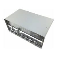
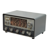
Refers to chassis removal for accessing and replacing tubes and dial lamps.
Provides detailed instructions for safely removing the receiver's chassis from its cabinet.
Details both mechanical and electrical procedures for adjusting the S meter.
Procedure for mechanically adjusting the S meter pointer to its correct alignment mark.
Procedure for electrically adjusting the S meter to indicate zero when the antenna is shorted.
Step-by-step guide for restringing the dial cords for the tuning and bandspread mechanisms.
General advice on receiver alignment, stressing it should only be performed by experienced personnel.
Lists the essential equipment needed to perform the receiver's alignment procedures.
Specifies the crucial initial control settings required before commencing alignment.
Detailed, step-by-step instructions for performing IF and RF alignment on the receiver.
Lists all capacitors used in the receiver, including Hallicrafters part numbers and specifications.
Lists resistors with schematic symbols, descriptions, and corresponding Hallicrafters part numbers.
Provides a list of all vacuum tubes and dial lamps with their part numbers for replacement.
Lists various control knobs, including those for Volume, Pitch, Sensitivity, and Band Selector.
Lists various other components like clips, retainers, cords, terminals, and cabinet parts.
Lists all the jacks, plugs, and sockets used in the receiver's construction.
Lists all the switches, including antenna, mixer, oscillator, and mode selection switches.
| Type | Communications Receiver |
|---|---|
| Modes | AM, CW |
| IF Frequency | 455 kHz |
| Audio Output | 2.5 W |
| Tube Count | 10 |
| Power Supply | 50-60 Hz |
| Image Rejection | 40 dB |