Do you have a question about the Hallicrafters SR-42 and is the answer not in the manual?
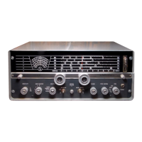
The Hallicrafters Model SR-42 is a compact, self-contained two-meter radio station designed for both 12-volt DC mobile and 117-volt AC fixed-station operation. It functions as a transmitter/receiver, primarily for amateur radio use on the 144 to 148 MC band. The unit comes factory-equipped with a transmitter crystal for 145.14 MC, with three additional positions for four-channel transmitter operation. The receiver is tunable across the entire 144 to 148 MC band. To operate, only a high impedance microphone with a push-to-talk switch and a suitable antenna are required for AC use. For 12-volt DC mobile operation, a Model MR-40 Mobile Kit is necessary, which includes a heavy-duty vibrator, a DC power cable assembly, and mounting hardware.
The SR-42 receiver is a double-conversion superheterodyne type, incorporating several advanced features for optimal performance. It includes a low-noise, neutralized-nuvistor RF stage and a low-noise triode first mixer, ensuring clear signal reception. A high-pass input filter helps to reduce unwanted interference. The receiver boasts eleven tuned RF and IF circuits, an automatic full-time noise limiter, and a Zener-regulated variable oscillator for stable operation. A crystal-controlled second oscillator and a double-spaced, copper-plate variable oscillator capacitor contribute to frequency stability and precision. Planetary drive for easier tuning and a dual tuning range provide greater bandspread. A calibrated "S" meter allows for signal strength indication. Audio output is provided by a heavy-duty speaker with a 3/4-inch voice coil and a one-ounce Alnico V magnet.
The transmitter section of the SR-42 is designed for reliable and efficient operation. It uses high-frequency type CR-23/U crystals, which help to reduce TVI (Television Interference). An automatic RF output meter switching system simplifies monitoring. A convenient "Frequency SPOT" switch allows users to tune the receiver to the transmission frequency. The unit offers four panel-switch selected crystal sockets, with provisions for an external VFO (Variable Frequency Oscillator). A microphone gain control allows for adjustment of modulation levels, and "Push-to-Talk" operation is provided for ease of use. A high-quality, sealed, changeover relay ensures smooth switching between transmit and receive modes. The hinged cover provides easy access to crystal sockets and tubes for maintenance.
The SR-42 is designed for user convenience with clearly labeled controls. The OFF-AF GAIN control powers on the unit and adjusts audio output. The REC. RANGE switch selects between 144-146 MC and 146-148 MC receiver tuning ranges, with corresponding dial calibrations. The TUNING control rotates the dial and variable oscillator capacitor for frequency selection. The XTAL-VFO switch is a five-position switch for selecting one of four crystals or an external VFO. GRID, PLATE, and LOAD controls are used to resonate the final amplifier input and output for maximum power transfer, adjusted for maximum upward meter deflection in transmit mode. The FREQ. SPOT switch allows the transmitter oscillator to be activated in receive mode to spot the transmission frequency on the receiver. The MIC. GAIN control on the rear chassis apron adjusts modulation percentage for maximum undistorted talk power. The METER ZERO adjustment on the rear chassis apron allows for electrical zeroing of the meter to compensate for component aging.
The SR-42 can be used with either a 117-volt AC source or a 12-volt DC negative ground system by selecting the appropriate power cord. For fixed installations, the standard two-contact molded plug is used. For mobile installations, the power lead with an in-line fuseholder should be connected directly to the positive (ungrounded) battery terminal, using No. 14 AWG wire or larger.
The SR-42 is wired for 12-volt negative-ground operation. If used in vehicles with a 12-volt positive-ground system, it is necessary to reverse the polarity of relay diode CR3 and relay electrolytic filter capacitor C68. Additionally, the zener filament regulator CR6 must be insulated from the chassis, and its connections reversed. A No. 14 AWG or larger wire must also be connected from the SR-42 chassis (screw terminal on rear) to the firewall or frame of the vehicle to complete the battery circuit.
The hinged cover provides easy access to pilot lights, tubes, and crystals. For service, the chassis can be removed by disconnecting the power cable, antenna, and microphone, then removing six screws from the cabinet bottom and sliding the chassis forward. The manual provides detailed alignment procedures for the 1650-KC IF, 20.15-MC IF, antenna and bandpass, variable oscillator, receiver oscillator multiplier coil, high pass filter coil, transmitter oscillator coil, and transmitter bandpass. It also includes voltage and resistance charts for troubleshooting. Hallicrafters maintains an extensive system of Authorized Service Centers for repairs, with warranty service provided free of charge within 90 days of purchase. After the warranty period, repairs are made for a nominal charge. Users are advised not to attempt service shipments to the factory without authorization.
| Brand | Hallicrafters |
|---|---|
| Model | SR-42 |
| Category | Receiver |
| Language | English |