20
21
NEXUS R3 WIRING Synchronised Pulsed Inputs (SPI)
Synchronised Pulsed Inputs are capable of
measuring the position, duty cycle, frequency or
state of a signal, as well as analog voltage inputs.
These inputs are suitable for sensors such as cam
position sensors, fuel composition sensors, road
speed sensors and flat shift switch.
Synchronised Pulsed Inputs are compatible with
digital (hall effect or optical) and analog (reluctor)
based sensors, have a maximum input voltage
rating of 25V and can measure up to 22.5kHz
Maximum frequency.
Specs:
• Number of channels: 6
• -10 to +10V digital input
• 0 to 5V analog input
• Selectable 1k pull-up to 5V
• -15 to +30V indefinite withstand
• 22.5kHz signal frequency max
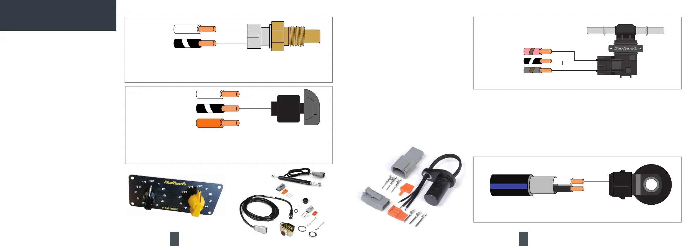
HT-011000 - HALTECH FLEX FUEL SENSOR
+12V (HBO6)
SIGNAL GROUND
SPI
SENSOR
KNOCK INPUT
GROUND
KNOCK SENSOR
Knock Inputs
A knock sensor detects engine knock and sends a
voltage signal to the VCU.
The NEXUS R3 VCU uses the knock sensor signal
to modify ignition timing if knocking occurs.
Knock detection can be performed by the VCU by
installing a compatible piezoelectric knock sensor
mounted to the engine block.
It is recommended that twin-core shielded cable
is used for knock sensors. Shields must be
terminated to battery ground at one end only.
Specs:
• Number of channels: 2
• -2.5 to +2.5V AC input only
• 160Hz to 48kHz signal frequency band
• +/-3V indefinite AC voltage withstand
• 50V indefinite DC withstand
Example Wiring Connections
Example Wiring Connections
Analog Voltage Inputs (AVI)
Analog Voltage Inputs are inputs to the VCU that
accept variable voltage signals from 0V to 5V
such as signals from pressure, temperature and
position sensors.
These inputs can also accept switched inputs that
change between two different voltage levels. The
On Voltage and Off Voltage set in NSP defines what
the thresholds are between the On and Off states.
Common examples of switched inputs include A/C
Request switch and intercooler spray switch.
AVIs have a software selectable 1K pull-up
resistor to 5V, which can be enabled or disabled
within the setup page.
Pull-up resistors are generally enabled for
temperature related sensors and switched to
ground inputs and disabled with external +5V
supply like a MAP sensor or throttle position
sensor .
Specs:
• Number of channels: 11
• 0 to 5V analog inputs
• 1000 samples per second
• Selectable 1k pull-up to 5V
• -10 to +30V indefinite withstand
• 1.5kHz signal frequency max
AVI
SIGNAL
GROUND
TEMPERATURE SENSOR
AVI
SIGNAL GROUND
SENSOR +5V
ROTARY TRIM MODULE
HT-010504
Pull-up resistors are generally enabled for temperature
related sensors and switched to ground inputs. The
following configuration requires the pull-up resistor be
enabled.
Sensors with a +5V supply do not require the
pull-up resistor be enabled, for example, rotary
trim modules. Any Sensor +5V pin can be used
with any Signal Ground pin for sensors.
 Loading...