Do you have a question about the Hamworthy 105he and is the answer not in the manual?
Installation must be performed by a competent person adhering to regulations and safety standards.
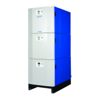
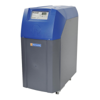
Details the boiler's features: fully modulating, high efficiency, cast iron, LMU control system, and direct flue connection.
Notes on un-vented systems, water treatment, reverse return layouts, and suitability for specific systems.
Information on optional header kits, external sensors, LPB bus communication, and cascade control.
Boilers are delivered pre-assembled; handle with care to avoid casing damage and ensure correct positioning.
Details on packaging for flue components, condensate trap, and optional header kits.
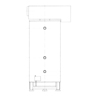
Specifies minimum ceiling height, clearances from flammable materials, and necessary access space for installation.
Provides dimensional data for 2, 3, and 4 boiler manifold installations for planning.
Requirements for floor/plinth, fireproofing, and adequate plantroom space for installation and access.
Details gas supply pipework standards, connection size, testing, purging, and inlet pressure.
Guidelines for flue termination, routing, construction, condensation management, slope, and pressure.
Covers tank requirements, pipe flushing, water treatment, and maximum working water pressure.
Ensures provision for condensate removal, use of non-corrosive pipework, and proper discharge.
Details earthing, isolation, voltage, fuses, cable size, and prohibition of time-clock switching.
Procedure for fitting the flue elbow to the boiler and securing the flue pipe.
Guidelines for connecting pipework, using local unions, and ensuring it is self-supporting.
Lists various electrical connections for supply, pumps, fault signals, and control inputs.
Ensures gas pipework is soundness tested and purged according to relevant standards.
Verification of correct ventilation and air supply to the plantroom.
Checks on pipework, system fill, pump operation, isolation valves, safety valve, and condensate connections.
Ensures the flue system is correctly designed, installed, clear, and traps are filled.
Verification that electrical connections are correct, isolatable, and external controls are operational.
Procedure for performing a gas system leak check using a manometer to ensure soundness.
Verification of electrical supply, safety limiter, control thermostat settings, and air inlet cleanliness.
Detailed steps for turning on gas/electrical supplies and initiating the ignition sequence.
Performing safety checks by disconnecting flame probe and gas valve during operation.
Procedure to access and view the flame ionization signal via the control panel display.
Steps to adjust the flow temperature setpoint using the control panel buttons.
Measuring CO2 levels at high and low fire to confirm correct combustion performance.
Refer to Controls Operation section for setting boiler parameters and timings specific to the installation.
Ensuring the owner is aware of operating instructions and receives the manual for reference.
Overview of the LMU controller, HMI display, and compatibility with BMS and peripherals.
Explains how to use the Info button to access and navigate through different information levels.
Steps to enter and navigate the extended information modes (b, c, d) for detailed data.
Table detailing the function and operation of each button on the control panel interface.
Lists available parameters for display, categorized by type: temperatures, process values, and setpoints.
Diagram illustrating the operation and display logic of the control system for user interaction.
Explanation of display characters, symbols, and their meanings for heating and DHW modes.
Illustrates the default display and how status and error codes are shown on the screen.
Shows how lockout codes are displayed and the procedure to adjust the heating circuit setpoint.
Lists default and adjustable parameters for end-users, including time of day and heating programs.
Describes how setpoints are initialized on startup or after a lockout reset.
Details functions like Chimney Sweep, Controller Stop, time setting, and operating modes.
A table detailing error codes, potential causes, and recommended actions for troubleshooting.
Explains the meaning of display codes and their corresponding LMU internal operating phases.
Overview of safety features like the temperature limiter and flame probe supervision.
Refers to section 8 for error messages and advises consulting Hamworthy if issues persist.
Lists common causes of boiler lockout such as igniter, gas valve, or pressure issues.
Recommends annual servicing, with an additional 6-monthly check, including controls and safety features.
Detailed procedure for servicing, including isolating power/gas and removing casing panels.
Steps for cleaning boiler flueways, including inspection panel removal and cleaning castings.
Procedure to remove, replace, and check the igniter and flame probe assembly.
Instructions for removing, replacing, and testing the safety temperature limiter.
Procedure for replacing the gas valve, emphasizing factory settings and gas soundness tests.
Steps to remove and replace the combustion fan assembly for different boiler models.
Lists part numbers for electrical components like controllers, sensors, igniters, and probes.
Lists part numbers for mechanical components like burners, gas valves, fans, and switches.
Provides contact details for service, spares, and technical support from Hamworthy Heating.
Provides general data including maximum input and output for different boiler models.
Details gas inlet connection size, pressure, flow rate, and target CO2 percentages.
Specifies normal supply voltage, maximum power consumption, and start/run current for boilers.
Notes on external wiring, earthing, isolation, and mains supply not being switched by time-clock.
Diagrams showing external control wiring for multiple boiler installations, including control options.
Illustrates the configuration of the Hamworthy-Trend IQ3 Remote Monitoring Unit.
Details flue diameter, allowable back pressure, gas temperature, and volume.
Guidelines for flue system installation, including condensation management and slope.
Specifies requirements for flue system materials, including robustness and corrosion resistance.
Guidance on safe flue discharge location to prevent combustion product entry into buildings.
Specifies limits for flue surface temperatures and clearances to combustible materials.
Advises on condensate discharge, avoiding freezing and using separate drains for modular systems.
Table showing equivalent lengths for flue components to calculate resistance for system design.
Details requirements for natural air supply via permanent vents for combustion and ventilation.
Guidelines for mechanical ventilation, including interlocking with boilers and airflow rates.
Details water circulation requirements, including minimum flow rates and pressure loss.
Specifies minimum system water pressure requirements for single and modular boiler installations.
Information on safety valve fitting and requirements, with tables for pipe sizes.
Illustrates typical piping layouts for vented and unvented systems with single pipe headers.
Details requirements for open vent and cold feed pipes, including bore size and pipe routing.
Discusses circulating pump requirements, performance checks, and system flushing.
Emphasizes maintaining minimum water flow rates to prevent heat exchanger damage.
Advises on using controls like mixing valves or flow switches to ensure minimum flow rates.
Lists parameters required for designing unvented (pressurised) hot water systems.
Schematic diagram for a single boiler system showing controls and connections.
Schematic diagram for a single boiler with a primary circuit system.
Schematic for a single boiler with external 0-10V control and multi-circuit system.
Schematic diagram for multiple boilers in a cascade system with primary circuit.
| Flow Temperature Range | 30 - 85°C |
|---|---|
| Boiler Type | Condensing |
| Fuel Type | Natural Gas |
| Max. Output (kW) | 105 kW |
| Flue Diameter | 125 mm |