Do you have a question about the Hamworthy Sherborne Series and is the answer not in the manual?
Advice on application and use of products from technical team and agents.
Service for restricted plant rooms, offering higher quality build.
Ensures equipment operates safely and efficiently by engineers or agents.
Routine servicing by engineers to inspect safety and integrity.
Rapid response service provided through head office and agents.
Service for replacement parts for current and discontinued products.
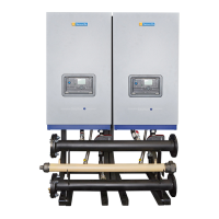
Details flue kits, mounting frames, and header kits.
Compatibility with external sensors, LPB Bus, and cascade control.
Procedure to check received boilers and ancillary packages against order.
List of items included in the accessory pack with quantities.
Requirements for a flat, level, strong, and fireproof installation location.
Pipework, connection, pressure, and isolation requirements for gas supply.
Feed/expansion tanks, pipework flushing, and pressure requirements.
Details flue termination, routing, construction, materials, and drainage.
Instructions for removal, pipework, and drainage of acidic condensate.
Requirements for earthing, supply voltage, fuses, and isolation.
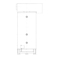
Instructions for positioning, fixing, and frame mounting the boiler.
Detailed installation steps for 80/125mm through-wall terminals.
Installation steps for 100/150mm extended flue lengths.
Installation steps for 100mm twin pipe room sealed systems.
Installation steps for 100mm twin pipe room sealed systems.
Installation steps for 100mm single pipe room sealed systems.
Details wiring terminals for various boiler functions and signals.
Ensures soundness and purging tests are completed.
Confirms correct ventilation and air supply to the plantroom.
Checks system fullness, venting, pressure, and pump operation.
Verifies correct flue design, installation, and clear passages.
Confirms electrical connections are correct, isolatable, and controls operational.
Procedure to check isolating valve and main gas valve for leaks.
Checks gas supply, ignition, sensors, and wiring before lighting.
Step-by-step guide for safely lighting the boiler.
Sequence of operations for boiler ignition and startup.
Verifies shutdown on gas isolation and re-ignition attempts.
Checks the ionisation signal strength during firing.
Procedure for setting the flow temperature setpoint.
Tests ignition controller by checking shutdown on gas valve closure.
Verifies inlet pressure for Natural Gas and LPG.
Site checks for CO2 and CO levels to confirm performance.
Description of control panel buttons and their respective functions.
Explanation of symbols and information displayed on the screen.
Selection of automatic, standby, normal, and reduced heating modes.
Accessing boiler information and diagnostic codes via the info button.
Accessing detailed operational and diagnostic data.
Display of fault codes and lockout conditions on the screen.
Obtaining additional fault information from internal error codes.
Table detailing potential causes and actions for error codes.
Initial setpoints after power-on or lockout reset.
Procedure for modifying user adjustable parameters.
Details special operating modes like Chimney Sweep and Controller Stop.
Mode for making measurements at maximum boiler output.
Allows manual adjustment of heat output in heating mode.
Explains setting and operation of the time of day function.
Meaning of LMU internal operating phases and their display codes.
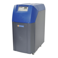
Details the layout and components of the boiler's control panel.
Schematic illustrating the boiler's electrical connections.
Detailed wiring diagram for the LMU (Local Module Unit).
Location, reset procedure, and causes for the limit thermostat tripping.
General guidance and contact information for fault finding assistance.
Lists common reasons for the boiler entering a lockout condition.
Procedures and checks required for the annual service.
Steps for preliminary checks and cleaning during annual service.
Detailed procedure for cleaning the heat exchanger.
Steps for re-assembling the boiler after servicing.
Part numbers and replacement steps for igniter and flame probe.
Part number and replacement steps for flow/return sensors.
Part numbers and replacement steps for the temperature limiter.
Part number and replacement steps for the gas valve and venturi.
Part number and replacement steps for the fan assembly.
Part numbers and replacement steps for the main control PCB.
List of recommended electrical spare parts with part numbers.
List of recommended mechanical spare parts with part numbers.
General and gas data for Natural Gas fired boilers.
General and gas data for LPG Propane fired boilers.
Details wiring requirements and mains supply considerations.
General requirements and recommendations for flue systems.
Design and installation guidelines for flue systems.
Data on waste gas volume and temperature for flue design.
Requirements for flue system suction and draught stabilisers.
Details allowable linear equivalent lengths for flue ducts.
Considerations for handling flue condensate discharge.
General air supply recommendations for combustion and ventilation.
Ventilation requirements for open flue systems.
Ventilation requirements for room sealed systems.
Requirements for mechanical ventilation systems.
Boiler water content and flow rate requirements.
Minimum system water pressure requirements.
Information on safety valve selection and capacity.
Pipe sizing and installation for open vent and cold feed pipes.
Requirement for an altitude gauge with isolating valve.
Maintaining required water flow rates whilst the boiler is firing.
Ensuring minimum water flow is maintained with external controls.
| Modulation Range | 5:1 |
|---|---|
| Boiler Type | Condensing |
| Fuel Type | Natural Gas |
| NOx Emissions | Class 5 |
| Casing | Steel |