Do you have a question about the Hamworthy Wessex ModuMax mk3 WM97/97H and is the answer not in the manual?
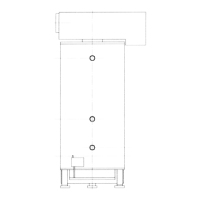
Details requirements for boiler placement and necessary clearances for access.
Ensures correct alignment and stability of boilers and manifold kits.
Covers gas pipework standards, connections, pressure, and isolation valve.
Details flue termination, routing, construction, and condensation management.
Specifies requirements for feed/expansion, pipework, flushing, and water pressure.
Addresses condensate removal from boiler and flue, material recommendations.
Outlines earthing, supply voltage, fuse ratings, wiring, and isolation requirements.
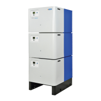
Instructions for safely dismantling and re-assembling boiler modules on site.
Guidance on connecting flue collector ducts and positioning the assembly.
Details the specific male thread connections for water flow and return.
Lists electrical connections available on each module for various functions.
Ensures gas installation pipework and meter are tested and purged.
Confirms correct ventilation and air supply to the plant room.
Checks system filling, venting, pressurization, pump operation, and valve status.
Verifies flue system design, installation, and clear passages.
Confirms electrical connections are correct, isolatable, and external controls operational.
Procedure to check the boiler's gas system for leaks using a manometer.
Explains the function of the safety limiter and its reset mechanism.
Details the controller's supervision of the flame and restart procedures.
Recommends annual servicing for trouble-free operation and checks.
Outlines the procedure for servicing each module, including safety precautions.
Instructions for replacing the igniter and flame probe ceramics.
Details how to remove and replace the flow and return sensors.
Procedure for replacing the temperature limiter and checking connections.
Provides guidance on replacing the gas valve assembly.
Steps for disconnecting and removing the combustion fan.
Instructions for isolating the gas supply and removing the venturi.
Guidance on disconnecting the burner assembly and inspecting components.
Procedure for unplugging and removing the ignition transformer.
Steps for removing and replacing the Navistem control PCB.
Instructions for disconnecting and removing clip-in modules from the Navistem.
Procedure for disconnecting and removing the display screen.
Details replacement of the low gas pressure switch.
Instructions for disconnecting and replacing the air pressure switch.
Guidance on checking the in-line fuse for the ignition transformer.
Instructions for replacing the air inlet filter material.