Do you have a question about the Hamworthy Wessex Modumax 100 series and is the answer not in the manual?
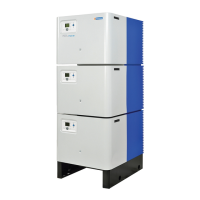
Details variations of Wessex ModuMax boilers by model and kW output.
Discusses optional features for Wessex ModuMax boilers, including kits and controls.
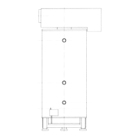
Specifies requirements for the floor or plinth and plantroom space for boiler installation.
Outlines regulations and requirements for gas supply installation and connection to the boiler.
Details flue termination, routing, construction, and material requirements for safe operation.
Covers requirements for feed, expansion, cold feed, open vent, and pressurised systems.
Specifies provision for condensate removal, pipework material, and discharge methods.
Details electrical safety, wiring, isolation, and supply requirements for the appliance.
Lists and describes the water connections provided on each boiler module.
Lists the electrical connections available on each boiler module.
Ensures gas installation pipework is tested, purged, and certificates are available.
Confirms correct ventilation and air supply to the plantroom.
Checks pipework, valves, pump installation, system filling, and isolation.
Verifies the flue system is correctly designed, installed, and clear.
Ensures electrical connections are correct, isolatable, and external controls are operational.
Details the procedure for checking the gas system for leaks before initial lighting.
Provides a step-by-step guide for safely firing up the boiler for the first time.
Explains how to access and display information via the Info button.
Identifies and explains the symbols and labels on the boiler's fascia control panel.
Describes the meaning of different characters and symbols displayed on the boiler's screen.
Shows the standard display layout and how the screen returns to it.
Explains how lockout codes are displayed and how to interpret them.
Details how to adjust the heating circuit setpoint temperature using the control panel.
Guides on modifying default settings to suit individual user needs.
Describes the setpoint initialization process on startup or after a lockout reset.
Introduces special functions available for boiler operation and measurement.
Explains the chimney sweep function for boiler startup and measurement.
Details the controller stop function for manual adjustment of heat output.
Emphasizes correct time setting for function operation.
Outlines the four different heating circuit operating modes selectable for the boiler.
Lists fault codes, their potential causes, and corresponding groups for diagnostics.
Describes how to check the ignition controller's operation and flame signal.
Details checking the gas supply pressure after boiler module checks.
Outlines site checks for confirming correct boiler performance and flue gas analysis.
Explains how the limit thermostat functions, trips, and potential causes of overheating.
Discusses issues related to the burner ignition controller and flame detection.
Recommends regular servicing for trouble-free operation and checks controls/safety features.
Details the procedure for annual servicing, including isolation and component checks.
Outlines the procedure for a four-year service, including heat exchanger cleaning.
Provides instructions for replacing the igniter and flame probe, noting fragility.
Details the removal and replacement of flow/return sensors.
Guides on replacing the temperature limiter and checking its setting.
Recommends replacing the gas valve and provides isolation and removal instructions.
Explains how to replace the combustion fan and associated components.
Details the replacement of the venturi, noting factory-set air inlet ring position.
Provides instructions for replacing the burner assembly and associated components.
Guides on replacing the ignition transformer, noting electrical isolation.
Details replacing the main control (LMU) unit, including electrical isolation.
Explains how to remove and replace clip-in modules for the LMU.
Guides on replacing the display screen and its associated components.
Details replacing the low gas pressure switch and checking connections.
Provides instructions for replacing the air pressure switch.
Addresses earthing, isolation, wiring, and mains supply requirements for boilers.
Introduces flue system recommendations and compliance with standards.
Details general requirements for natural draught and room sealed flue systems.
Recommends using specified waste gas volumes and temperatures for flue design.
Outlines material requirements for flue systems, considering corrosion and freezing.
Addresses flue system design acknowledging boiler fan pressure and recommending draught stabilizers.
Advises on provisions for flue pipe disconnection for servicing.
Ensures safe operation and dispersion of combustion products, considering terminal location.
Specifies maximum surface temperatures for combustible materials near the flue.
Advises on flue system placement to avoid accidental damage and ensure clarity.
Details condensate removal, pipework, and protection from freezing.
Provides general guidance on air supply for combustion and ventilation.
Covers requirements for permanent air vents for boiler room ventilation.
Details requirements for mechanical ventilation systems and their interlocks.
Outlines requirements for water circulation systems, including indirect cylinders and insulation.
Provides minimum system water pressure requirements based on boiler configuration.
Discusses the importance of safety valves and their capacity requirements.
Specifies requirements for open vent and cold feed pipes, including bore and protection.
Recommends fitting an altitude gauge with an isolating valve.
Advises fitting a thermometer to indicate water flow temperature.
Details the location and type of drain valves required for the boiler and system.
Discusses pump requirements, performance checks, and system flushing.
States minimum water flow rates that must be maintained to prevent heat exchanger damage.
Refers to table for waterside hydraulic resistance.
Emphasizes ensuring minimum flow rates and suggests flow switches.
Suggests fitting a frost thermostat for protection.
Refers to layout for unvented systems and pressurisation unit sizing.