EasyManua.ls Logo

handtmann 33501 - User Manual

Default Icon
30 pages
Print Icon
To Next Page IconTo Next Page
Loading...
Translation
Operating manual
Safety relief valves
33501, 33502, 33503, 33521,
33601, 33602, 33603, 33621
BA(k)_033501.06_EN

Questions and Answers

  • A
    adam89Aug 5, 2025
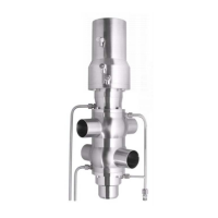
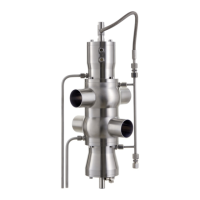
    What to do if the handtmann Control Unit safety relief valve does not open?
    • B
      Blake ChapmanAug 5, 2025
      If the handtmann Control Unit's pneumatic safety relief valve doesn't open, several factors could be at play. It might be due to a jammed valve seat, which can be resolved by manually lifting the valve and cleaning the valve seat. Ensure the pressure setting is correct and sufficient for opening. The valve rod's mobility should be checked manually. Confirm that the compressed air supply is at least 5 bar and inspect the compressed air hose. A faulty solenoid valve or electrical control could also be the cause, so check the solenoid valve.
  • N
    Nancy WoodAug 20, 2025
    Why the handtmann 33501 safety relief valve does not close?
    • L
      Lori Clayton MDAug 20, 2025
      If the handtmann Control Unit's pneumatic safety relief valve isn't closing, it could be due to several reasons. The lifting nut might be screwed against the housing, which requires you to screw the lifting nut upwards. A solid body might be misaligned in the valve seat, requiring cleaning of the valve housing and seat. The actuator spring could be blocked or broken (the defective actuator may only be repaired by the manufacturer), the pressure bleeding could be defective (check the solenoid valve), or the sealing could be defective, necessitating a change of sealings.

Summary

0 Foreword

1 General

1.1 Manufacturer

Provides contact details and location of the manufacturer.

1.2 Proper application

Defines the intended use and applications for safety relief valves.

1.3 Improper application

Lists conditions considered as improper use and consequences.

1.4 Duties of operator

Outlines the responsibilities of the operator for safe and correct use.

2 Safety Information

2.1 Symbols

Explains the meaning of different warning symbols used in the manual.

2.2 Hazards and Safety Instructions

Details potential hazards and corresponding safety measures for service personnel.

3 Notes

3.1 Notes on transport

Provides safety instructions and guidelines for transporting the valve.

3.2 Instructions for Delivery and Performance

Details procedures for checking delivery and handling performance.

3.3 Storage Instructions

Specifies conditions for proper storage of the valve.

4 Technical Description

4.1 Technical Data

Lists key technical specifications, materials, and performance data.

4.2 Identification of components

Explains how to identify components using nameplates and markings.

4.3 Valve types

Describes different valve types, their specifications, and optional equipment.

5 Performance Data

6 Operation

6.1 Valve actuator

Explains the function and operation of the valve actuator.

6.2 Valve Tightness; Leak

Describes issues related to valve seat sealing and leakage.

6.3 Operating Characteristics

Explains how the safety relief valves operate and are set.

6.4 Valve cleaning; CIP

Provides instructions for cleaning the valve, including CIP processes.

7 Disassembly

7.1 Assembly instructions

Lists essential precautions and steps before starting disassembly or assembly.

7.2 Disassembling manual safety relief valves - Types 33501, 33502, 33503, 33521

Step-by-step guide for disassembling manual safety relief valves.

7.3 Disassembling pneumatic safety relief valves - Types 33601, 33602, 33603, 33621

Step-by-step guide for disassembling pneumatic safety relief valves.

8 Installation and Commissioning

8.1 Installation Instructions

Provides detailed instructions for installing the safety relief valves correctly.

8.2 Assembly

Details the steps for assembling the safety valve after installation.

9 Trouble shooting

10 Maintenance

10.1 Maintenance

Provides general notes and precautions for maintenance work.

10.2 Inspection and Maintenance Intervals

Specifies recommended intervals for inspection and maintenance.

10.3 Function Checks

Outlines procedures for performing function checks on the valve.

10.4 Seals

Illustrates and lists the seals used in manual and pneumatic safety relief valves.

10.5 Spare parts

Lists available spare parts with part numbers for different valve types.

11 Additional Equipment

11.1 Heating insets

Details heating insets, their specifications, and wiring diagrams.

12 Disposal

handtmann 33501 Specifications

General IconGeneral
Brandhandtmann
Model33501
CategoryControl Unit
LanguageEnglish

Related product manuals