7
OPERATIONAL GUIDE
POWER CONNECTION
Plug the 12 VDC adapter into the power supply socket.
Notes: These instruments use non volatile memory to retain the
pH, mV, temperature calibrations and all other settings, even when
unplugged. Make sure a fuse protects the main line.
ELECTRODE AND PROBE CONNECTIONS
For pH or ORP combination electrode connect to the BNC connector on
the back of the instrument.
For electrodes with a separate reference connect the electrode’s BNC
to the BNC connector and the reference electrode plug to the reference
socket.
For temperature measurements and automatic temperature compensa-
tion connect the temperature probe to the appropriate socket.
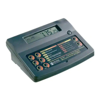
INSTRUMENT START-UP
• Turn the instrument on by pressing the ON/OFF switch located on
the rear panel.
• All LCD segments are displayed while the instrument performs a
self test.
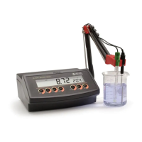
pH MEASUREMENTS
Make sure the electrode and the instrument have been
calibrated together before taking pH measurements.
• Submerse the electrode and the temperature probe
approximately 3 cm (1¼”) into the sample to be
tested and stir gently. Allow time for the electrode
to stabilize.
• The pH is displayed on the primary LCD and the temperature on
the secondary LCD.
• If the pH reading is out of range, the closest full scale value will
be displayed blinking on the LCD.
 Loading...