5
APM-001e
AUG 2015
ELECTRICAL CONNECTIONS
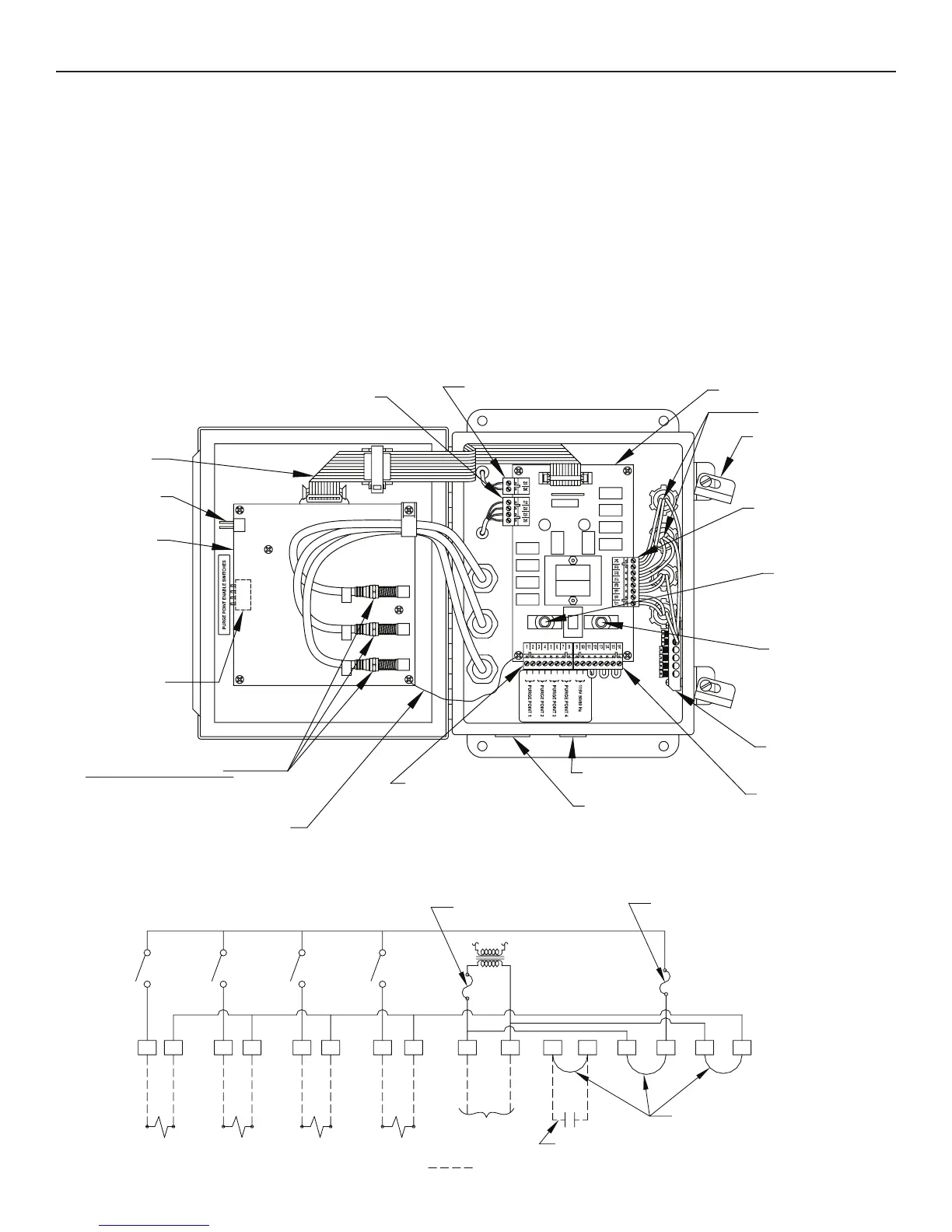
The standard electrical requirement for the APM is 115V
50/60 Hz. Also available is 230V 50/60 Hz. Main supply
voltage fluctuations should not to exceed ± 10% on nominal
voltage. Connect APM to a dual pole external switch or
circuit breaker suitable for full disconnection. Locate this
switch or circuit breaker nearby. The control cabinet has
a bottom ½” knockout for power connection and bottom
3/4” knockout for individual purge point solenoid valves
(See Figure 4). Any additional knockouts, if necessary,
should be made on the bottom of the control cabinet. A
grounding block inside the control cabinet is provided for 3
wire purge point solenoid coils. Carefully study the wiring
diagram below (Figure 5) to avoid electrical short circuits.
Connect electrical wiring from each purge point solenoid to
the remote purge point solenoid plug-in connector screw
terminals (1 through 8) plus the grounding block. Normally,
the voltage of the remote purge point solenoid valves is the
same as the purger. However, if the purge point solenoid
valve coil voltage is different, simply remove and discard
the factory installed jumpers between terminals 13 & 14 and
15 & 16. Bring the purge point solenoid line (L1) connection
to terminal 14 and neutral (L2) to terminal 16.
SECTION 2 ELECTRICAL INSTALLATION & OPERATION
RESET PINS
NLLLN NNLLN
PLUG-IN CONNECTOR
POWER BOARD
COAXIAL CONNECTORS
1/2'' KNOCKOUT
POWER / INTERLOCK
PLUG-IN CONNECTOR
GROUNDING BLOCK
POWER BOARD
REPLACEABLE 3 AM
REMOTE PURGE
POINT SOLENOID
REPLACEABLE 3 AM
PURGER SOLENOID
PLUG-IN CONNECTOR
CONTROL BOX LATCH
CONTROL BOARD
D
1
PLUG-IN CONNECTOR
3/4'' KNOCKOUT
REMOTE PURGE
POINT SOLENOID
PLUG-IN CONNECTOR
2
3
FUSE (P/N 20-1698)
FUSE (P/N 20-1698)
2-LOW SIDE LEVEL SENSOR
1-DRAINER LEVEL SENSOR
3-HIGH SIDE LEVEL SENSOR
T
ENABLE SWITCHES
F6A
F6B
E
RTV SILICONE SEALANT
AND SHIELD
GROUNDING WIRE
CONTROL CABINET (INSIDE VIEW)
Figure 4
WIRING DIAGRAM
Figure 5
16151413121110987654321
#1 #2 #3 #4
PURGE POINT SOLENOID VALVES
#1
FACTORY-INSTALLED JUMPER
OPTIONAL INTERLOCK
(REMOVE JUMPER IF USED)
#2 #3 #4
FIELD INSTALLED WIRING
LINE
NEUTRAL
LINE VOLTAGE
POWER BOARD REPLACEABLE
3 AMP TYPE F FUSE (P/N 20-1698)
REPLACEABLE 3 AMP TYPE F FUSE
REMOTE PURGE POINT SOLENOID
(P/N 20-1698)
 Loading...