11
A100b
JAN 2009
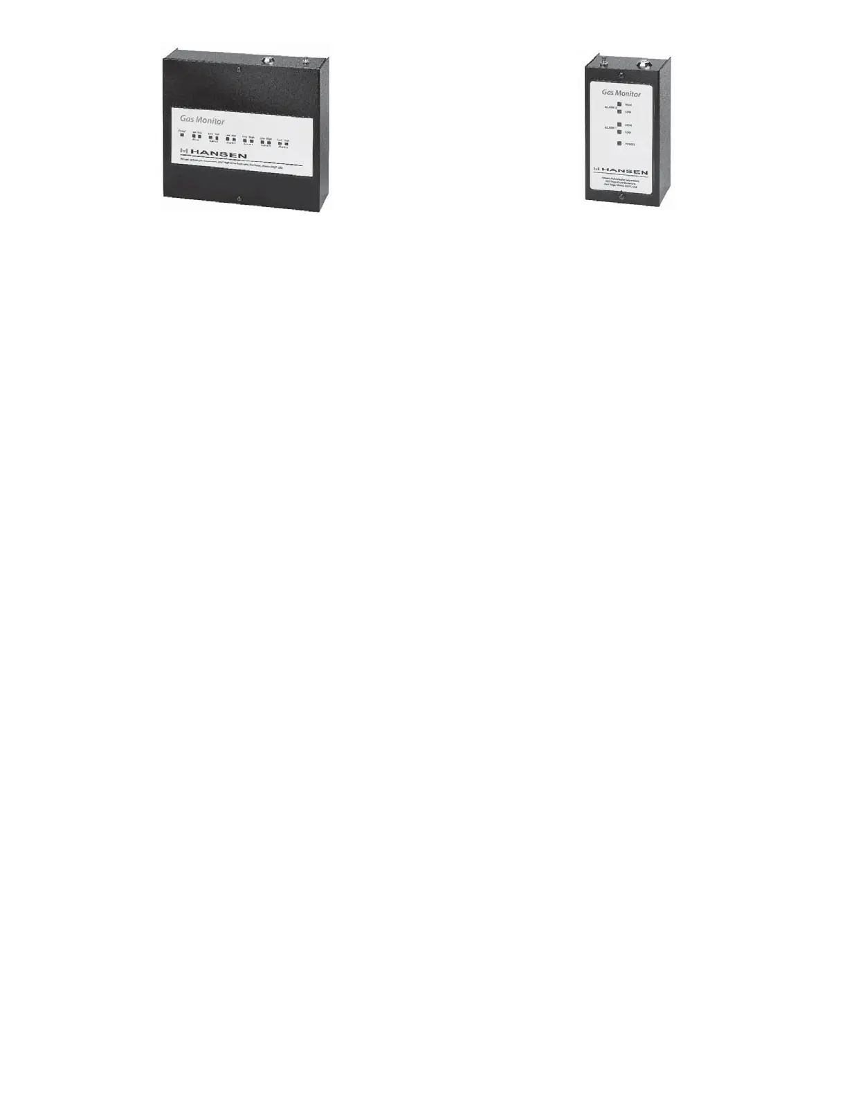
HLM6 - Six Channel Monitor
HLM2 - Two Channel Monitor
KEY FEATURES–MONITORS
120 or 230V AC power•
Audible alarm•
Visual power indicator•
(2) alarm and (1) fault relay outputs - Model HLM6•
(2) alarm relay outputs - Model HLM2•
CE approved•
TYPICAL SPECIFICATIONS
Two Level Monitors: Model HLM2 and Model HLM6
Low-level Alarm:
- Visual Warning Yellow LED
- Audible Warning Intermittent
- Relay SPDT Energized
High level alarm:
- Visual Warning Red LED
- Audible Warning Continuous
- Relay SPDT Energized
The Model HLM2 two channel monitor has the alarm
built in.
The Model HLM6 six channel monitor has an externally
mounted horn. A device rated up to 12V DC at 100mA
maximum may be connected to CN11, see Fig. G. The
high level SPDT relay may be set for Normal Operation
(normally closed position with no power) or Fail-Safe
Operation (relay energized when power to monitor is
applied). The Fail-Safe Operation is initialized by setting
Jumper JP1 over pins 2 and 3.
Low level alarms reset automatically when the detected
gas dissipates. High level alarm condition requires a
manual reset (user to press the reset button on the
topside of the monitor). Please note that a high level
alarm condition can only be reset 30-60 seconds after
the gas clears from the sensor.
The audible alarm produced by the horn may be disabled
by turning the key switch off. The key switch is located
on the topside of the monitor.
TECHNICAL SPECIFICATIONS–MONITORS
Operating Temperature Range: 32ºF (0ºC) to
125ºF (50ºC)
Output: 2 SPDT dry contact relays (alarms) - 10 amp
@ 230V AC
1 SPDT dry contact relay (fault output) - 10 amp @
230V AC (HLM6 Model only)
Power Required: 120V AC (230V AC available)
Power Consumption:
300mA @ 120V AC, 50/60 Hz (HLM6)
150mA @ 230V AC, 50/60 Hz (HLM6)
100mA @ 120V AC, 50/60 Hz (HLM2)
50 mA @ 230V AC, 50/60 Hz (HLM2)
Audible Alarm:
HLM2 - internal 80 dB,
HLM6 - external 110 dB/12V DC
INSTALLATION INSTRUCTIONS
The Hansen Technologies Gas Detection Monitor should
be located in an accessible area, away from moving
equipment that could accidentally come in contact with
the unit. Avoid thermal extremes (close to heaters).
Monitor must be protected from direct strong drafts/
airflows and areas where falling water or condensing
moisture is present.
WIRING OF GAS DETECTION MONITORS
Install the Hansen Gas Detection Monitor on a wall or in
an electrical panel in an area where operating personnel
will easily monitor the leak detection system. There are
three mounting holes on the back of the panel. Remove
the front cover and disconnect the grounding wire to
access the mounting holes. Attach the monitor to the
wall using the appropriate mounting screws.
Hansen Gas Detection Monitors are available for use
with two or six sensors. For larger systems, use multiple
Gas Detection Monitors. Alternately, the gas sensors
can be used directly with a customer supplied computer
or PLC and software.
Connect specified AC power to the Gas Detection
Monitor. Size the circuit for a minimum 5 amps for 120V
or 2 amps for 230V. Use two wire plus ground with
minimum 18 gauge wire (.823mm sq.) for 120V service
or .75mm sq. wire for 230V service. Bring power into
the bottom of the enclosure. Seal any excess conduit or
cable entries. See page 13 for terminal connections.
Extreme Gas Sensor requires an additional external
24V AC or DC power supply. Refer to Fig. K for wiring
details.
 Loading...