12
A100b
JAN 2009
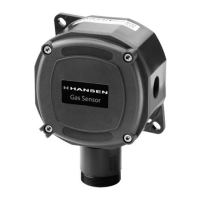
Maximum Power Wiring Length to a Monitor
120V
System
230V
System
Wire
Size
Maximum
Ohms/Wire
Length Length
Ft m Ft m
HLM2
200 60.9 120 40
22 Gauge
7/.2mm
3.52
500 150 300 100
18 Gauge
7/.386mm
HLM6
500 150 300 100
22 Gauge
7/.2mm
8.8
1300 430 700 230
18 Gauge
7/.386mm
TABLE 2
Note: There is a 5 minute delay before the green power light
on the gas monitor is energized. This is to allow the Gas
Sensor to stabilize and not give off false information.
The Hansen models HLM2 and HLM6 have both low
level alarm and high level alarm single pole double
throw (SPDT) relays. HLM2 low level alarm relay is on
the CN5 terminal and the high level alarm relay is on
the CN4 terminal.
The Hansen model HLM6 has the low level alarm on CN10
terminal and the high level alarm on CN9 terminal. In
addition, model HLM6 has a fault output on CN12.
The HLM6 includes two additional outputs on terminal
block CN11. CN11 (+12V and BUZZ) are used to drive an
external alarm horn (included). CN11 (+12V and 0V) is
an uncommitted, fuse (FS8) protected, voltage output
(12V DC@100mA) available to power external relays,
etc. It may be used in conjunction with the low level,
high level and/or fault output to provide a switched 12V
DC output.
In addition to the power line fuses or circuit breakers,
each monitor has an internal power line fuse. The fuse
rating is listed in Table 3 below.
MONITOR 120V AC 230V AC
HLM2 100mA 50mA
HLM6 315mA 160mA
TABLE 3
RELAY SET POINTS FOR GAS DETECTION
MONITORS
Gas Detection Monitors are equipped with two relays—
low level and high level. Shipped from the factory, the
relays are set for 20% and 60% of the output of the
sensor. In other words, a 250 PPM sensor will activate
the low level alarm at 50 PPM and the high level alarm
at 150 PPM. The relay settings can be field adjusted.
Refer to page 13 for details.
CALIBRATING HLM6 MONITOR
Use a voltmeter to monitor the voltage on the calibration
pins. The voltage range is from 0.4V DC to 2.0V DC.
The voltage range corresponds to the 4-20mA range.
(ie. 0.4V DC equals 4mA, 2.0V DC equals 20mA).
For the low level alarm relay setting, measure the voltage
across Calibration Pins 2 and 4. Set the desired low
level alarm relay using the Low Level Alarm Pot which
is located closest to the calibration pins. This setting
applies to the six channels.
For the high level alarm relay setting, measure the voltage
across Calibration Pins 1 and 4. Set the desired high
level alarm relay using the High Level Alarm Pot which is
located furthest from the calibration pins. This setting
applies to the six channels.
CALIBRATING HLM2 MONITOR
Use a voltmeter to monitor the voltage on the calibration
pins. The voltage range is from 0.4 V DC to 2.0V DC.
The voltage range corresponds to the 4-20mA range.
(i.e. 0.4V DC equals 4mA, 2.0V DC equals 20mA).
For the low level alarm relay setting, measure the voltage
across Calibration Pins 2 and 4. Set the desired low
level alarm relay using the Low Level Alarm Pot which
is located closest to the calibration pins. This setting
applies to both channels.
For the high level alarm relay setting, measure the voltage
across Calibration Pins 1 and 4. Set the desired high
level alarm relay using the High Level Alarm Pot which is
located furthest from the calibration pins. This setting
applies to both channels.
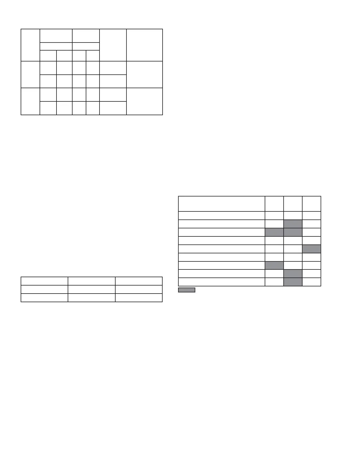
HLM6/HLM2 RELAY OPERATION
EVENT
LOW
LEVEL
RELAY
HIGH
LEVEL
RELAY
FAULT
RELAY
(CN12)
No Power
*
Fail Safe ON (No Alarms)
Fail Safe ON (Low Level Alarming)
Fail Safe ON (High Level Alarming)
Fail Safe ON (Low & High Level Alarming)
Fail Safe OFF (No Alarms)
Fail Safe OFF (Low Level Alarming)
Fail Safe OFF (High Level Alarming)
Fail Safe OFF (Low & High Level Alarming)
= Relay Energized
* Fault Relay (CN12) normally open contacts are closed with
no power.
The High Level Relay (CN9) is the only relay linked to the Fail
Safe. Fault Relay (CN12) only available on the HLM6. Use Fail
Safe OFF events for HLM2.
There is a 5 minute delay before the green Power LED on the
monitor is energized. During the delay, if the input current to
any channel is less than 0.9mA the High Alarm LED and the
Fault Output Relay (HLM6 only) will be energized.
(HLM6) After the delay, if the input current to any channel is
less than 0.9mA
Fail Safe jumper “ON”: High Level Relay energized
Fail Safe Relay energized
High Level Alarm LED energized
Audio output not active
Fail Safe jumper “OFF”: High Level Alarm LED energized
Fail Safe Relay energized
Audio output not active
(HLM2) After the delay, if the input current to any channel is
less than 0.9mA the High Level Alarm LED is energized and no
audio output.
 Loading...