18
A100b
JAN 2009
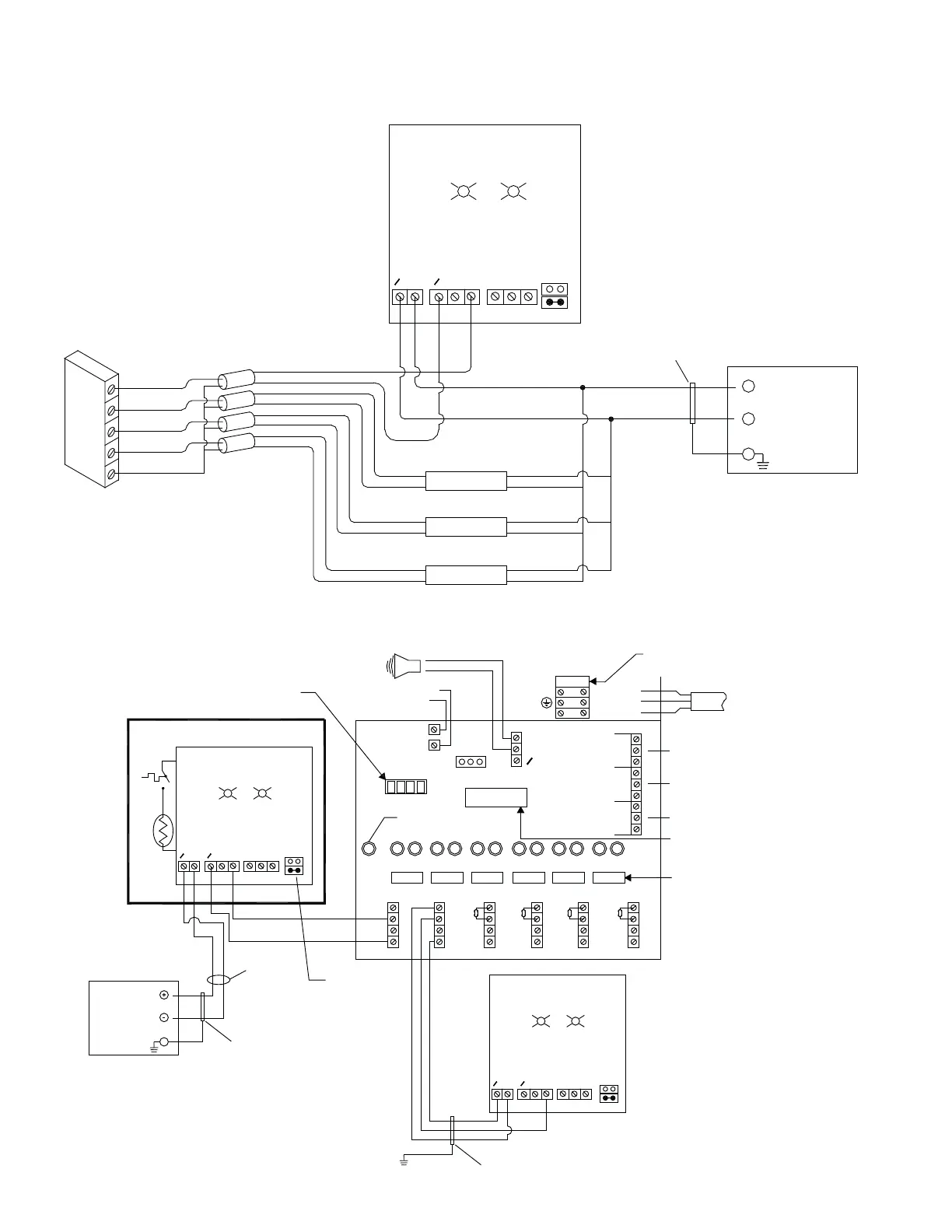
PLC 4 PT. ANALOG IN MODULE (CURRENT)
FIG. J
TYPICAL WIRING DIAGRAM HLM6 TO EXTREME GAS SENSOR
FIG. K
GREEN RED
V
+V
V
INOCOMNC
0
0 V
Power Supply
24V AC/DC
EARTH GRD
Multi-Wire
Cable Shield
*REMOTE SENSOR
+
-
INPUT #1
INPUT #2
INPUT #3
INPUT #4
ANALOG GND
REMOTE SENSOR
REMOTE SENSOR
REMOTE SENSOR
* Wiring is the same for AC or DC Power Supply.
Voltage selector must match external power supply.
A
D
POWER
IN
GREEN RED
EXTREME GAS SENSOR
V
+V
V
INOCOMNC
0
0
HORN
- LINE
- GROUND
- NEUTRAL
+12V
BUZZ
0 V
CN11
FAIL
SAFE
OFF ON
FUSE
CAL
L
N
GYRYRYRYRYR RY
CN1
1
2
3
4
CN2
1
2
3
4
CN3
1
2
3
4
CN4
1
2
3
4
CN5
1
2
3
4
CN6
1
2
3
4
FUSE FUSE FUSE FUSE FUSE FUSE
N/0
N/C
N/0
N/C
COM
N/0
N/C
COM
COM
CN10
CN9
CN12
POWER ON LIGHT
MODEL HLM6
V
*
Remove Resistor when connecting a senso
*** *
12
34
LOW LEVEL ALARM POT
CALIBRATION PINS
HIGH LEVEL ALARM POT
LOW LEVEL
ALARM
HIGH LEVEL
ALARM
FAULT OUT PUT
FUSE
GMC-200mA 250V
120V: GMC-315mA 250V
230V: GMC-160mA 250V
120V/230V: GMC-315mA 250V
Valve: 3.3K ohm
1
Power Supply
24V AC/DC
EARTH GRD
Multi-Wire
Cable Shield
18 AWG.
GREEN RED
V
+V
V
INOCOMNC
0
0 V
Multi-Wire
Cable Shield
* Wiring is the same for AC or DC power supply.
Voltage selector must match external power supply.
A
D
A
D
External Power Supply
Voltage Selector