Hantek1025G
USER’S MANUAL 23
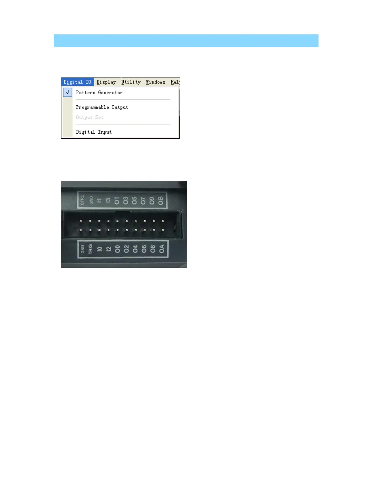
3.6 Digital Input/Output
Select Menu “Digital IO”, you can change the current digital IO mode.
At the digital IO terminal on the Hantek1025G, there are 20 digital IO pins, 2 GND, 1 TRIG, 1
CTRL, 4 Digital In Pins and 12 Digital Out Pins.
1. Pattern Generator:
The vertical resolution of Hantek1025G is 12bits. If selected this mode, you can get the each
bit of the value by testing the digital out pins. The LSB is O0, and OB is MSB. By Logic
Analyzer, you will get a good view.
For example: Use the Hantek1025G to generate a 1 KHz, 2.00V, sine waveform at the BNC
output channel, there will be synchronizied square waveforms outputs from O0- OB.
Connect the O0- OB to logic analyzer and you will see the digital waveforms for the analog
Sine wave.
 Loading...