
J
Jessica WagnerJul 30, 2025
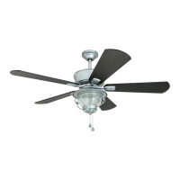
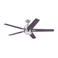
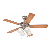
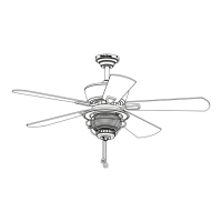
Why is my Harbor Breeze MERRIMACK II wobbling excessively?
- RRebecca YoungJul 30, 2025
Excessive wobbling in your Harbor Breeze Fan can stem from several causes. First, check and tighten all screws that hold the fan blades to the blade arms and the blade arms to the motor. If the issue persists, try switching one blade with a blade from the opposite side, or use a blade balancing kit. Also, turn off the power and ensure the mounting bracket is securely attached to the electrical outlet box and that the outlet box itself is secure. If the fan is too close to a vaulted ceiling, consider using a longer downrod or moving the fan. Finally, lift up the yoke cover and tighten the set screws on the yoke until secure.