Do you have a question about the Harbor Breeze MERRIMACK II 41125 and is the answer not in the manual?
| Brand | Harbor Breeze |
|---|---|
| Model | MERRIMACK II 41125 |
| Type | Ceiling Fan |
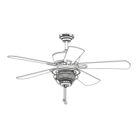
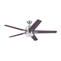
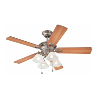
| Blade Span | 52 inches |
| Number of Blades | 5 |
| Motor Type | AC Motor |
| Light Kit | Yes |
| Control Type | Pull Chain |
| Finish | Brushed Nickel |
| Remote Control Included | No |
| Reversible Motor | Yes |
| Indoor/Outdoor Use | Indoor |
| Mounting Options | Downrod |
| Mounting Type | Downrod |
Follow manual, disconnect power, ensure proper electrical codes and clearances for safe installation.
Covers outlet box integrity, dimmer switch use, wire connector limits, blade handling, and using specified parts.
Ensure all parts are present by comparing with lists; note estimated assembly time and required tools.
Ensure power is off before installation to prevent injury or death.
Choose between standard, angle, or closemount installation based on ceiling type and height.
Confirm fan blades maintain required clearance from floor and obstructions for safe operation.
Securely attach the mounting bracket to the outlet box using appropriate hardware.
Remove preassembled motor screws and blocks from the motor assembly.
Remove downrod pin/clip and loosen set screws in the yoke for assembly.
Insert downrod through canopy/cover and feed wires through for connection.
Slide downrod into yoke, align holes, and secure with pin, clip, and set screws.
Trim lead wires if necessary and strip insulation for easier wiring connections.
Install the ball end of the downrod into the mounting bracket, aligning tab and slot.
Remove canopy cover; downrod, canopy cover, and yoke cover are not used in this installation.
Remove closemount screws from motor, align canopy, and re-install screws to motor assembly.
Hang the canopy on the mounting bracket hook to free hands for the wiring process.
Connect household supply wires to fan wires (green, white, black, blue) using wire connectors as per diagram.
Wrap connectors with tape, push wires into outlet box, ensuring no bare wire is visible.
Align canopy over bracket screws, place keyholes, rotate clockwise, and tighten screws securely.
Partially insert blade screws and washers through blades and into blade arms; tighten securely.
Attach blade arms to the underside of the motor assembly using motor screws.
Loosen fitter plate screws, align light pan key slots, turn clockwise, and tighten screws.
Connect 9-pin connectors and attach light kit using light pan screws.
Install bulbs, lift glass globe, secure with finial cap and finial.
Align light frame grooves with bumps on light kit, turn clockwise until locked.
Attach pull chain extensions and turn on power supply to complete assembly.
Adjust reverse switch for summer (sun icon, downward airflow) or winter (snowflake icon, upward airflow).
Use fan pull chain for speed (HIGH, MEDIUM, LOW, OFF) and light pull chain for ON/OFF.
Tighten screws twice yearly; clean housing with a soft brush or lint-free cloth.
Use max 40W E26-base LED, CFL, or incandescent bulbs; avoid halogen.
Check reverse switch, wall switch, power/fuse, and wire connections for issues.
Tighten blades/arms, balance blades, secure mounting bracket, check outlet box integrity.
Check blade tightness, cracked blades, wall control compatibility, outlet box, and mounting bracket security.
Re-install bulbs, ensure light kit wire plugs are connected, check wire connections.
Covers defects in workmanship/materials; excludes glass, plastic blades, misuse, improper installation, and environmental damage.
Present proof of purchase; costs of removal/reinstallation are buyer's responsibility.
Lists parts (A, D, E, etc.) with corresponding part numbers for different models.