Page 8 ;&(%$*4.8"4,7%<'*#$"&8#=%/7*,#*%4,77%>?@@@?@AA?BCDC1 Item 58703
EF;6GH IJ6KFGLIM NFLMG6MFMO6FEE6NPQH
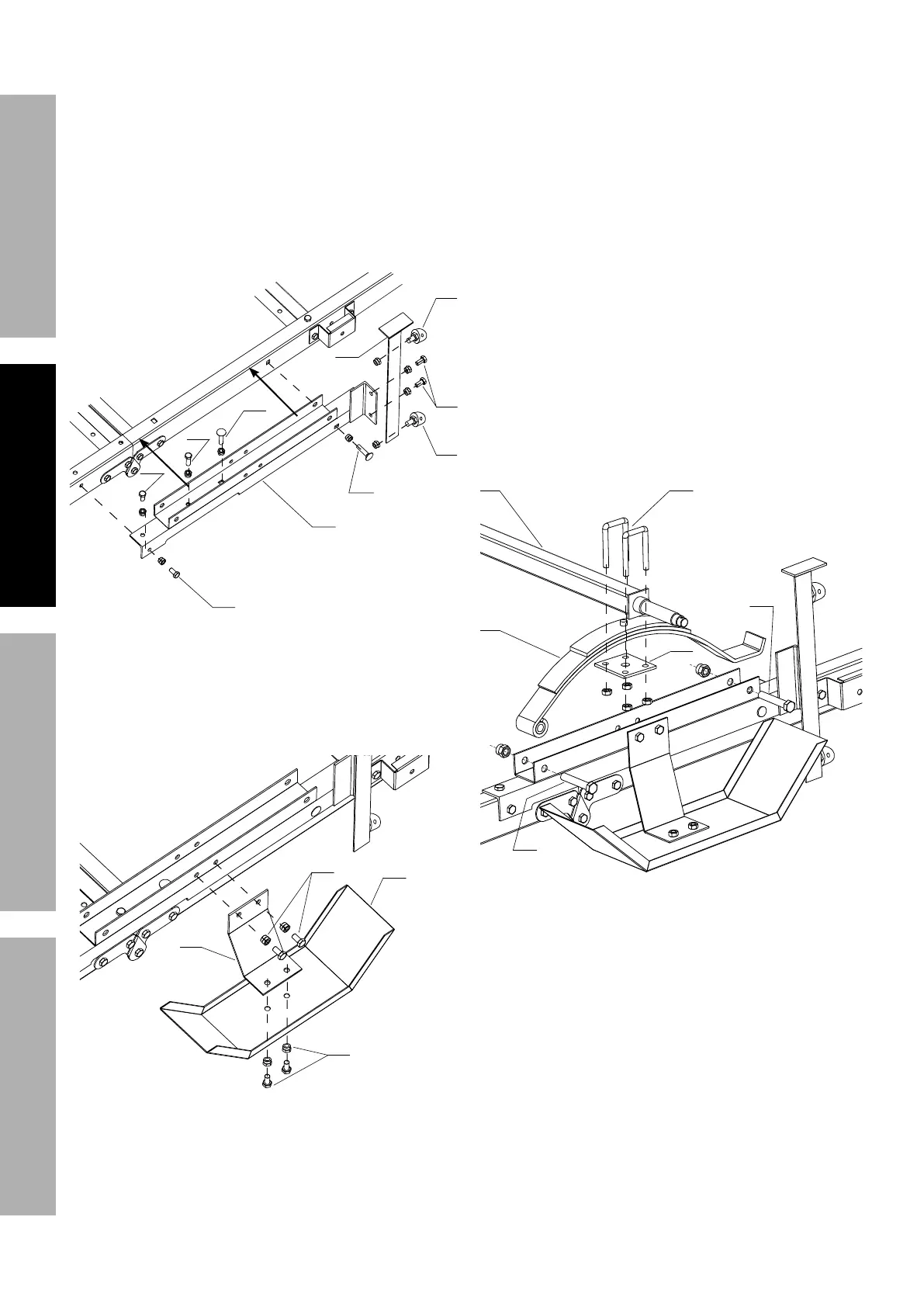
10. Place Right Spring Hanger (41) and Left Spring
Hanger (19) over Right and Left Side Rails.
11. Secure using:
VHWVRI%ROWV0[DQG1XWV0
VHWRI%ROW0[DQG1XW0
VHWVRI&DUULDJH%ROWV0[DQG01XWV
12. Attach Right Caster Bracket (23) and Left
Caster Bracket (22) to Spring Hangers, using
VHWVRI%ROWV0[DQG1XWV0
13. Attach 4 Casters (21) to Caster Brackets.
\B
\B
\A
Z>
ZZ
ZZ
ZZ
]>
]>
]\
14. Attach Fender Brackets (24) to left and
right Fenders (25) using four sets of
0[%ROWVDQG01XWV
15. Attach Fender assemblies to left and
right Spring Hangers using four sets of
%ROWV0[DQG1XWV0
ZZ
ZZ
]B
]Z
16. Attach Springs (8) to left and right Spring
Hangers with spring eyes facing forward,
XVLQJVHWVRI%ROWV0[DQG1XWV
M12 (20).
Q*,V*%$.*#*%P&7$#%7&&#*%
$*5/&(,("7U%$&%,77&)%/(&/*(%
,##*5+7U%"8%$.*%8*Y$%#$*/#1
17. Place Axle (7) on top of Springs.
Align depressions on Axle with
protrusions on Springs.
18. Remove nuts from Axle U-Bolts (9).
On both ends of the Axle, place
Spring Plates (6) under Springs and
insert Axle U-Bolts (9) down over
Axle and through mounting holes in
Spring Plates. Adjust Spring Plates
slightly to allow holes to line up.
19. Secure Axle U-Bolt with nuts, then tighten
0[%ROWVDQG01XWVOHIWORRVH
in step 16 to secure Spring assemblies.
G&(<'*%FY7*%W?P&7$%8'$#%$&%>B%2$1?7+1
]^
]^
C
@
A
D