5
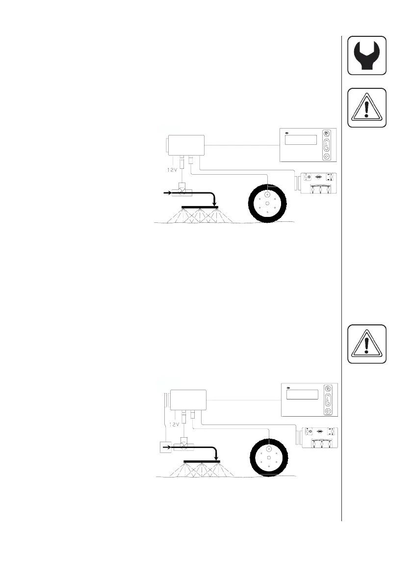
HM 1500 Monitor with manual control unit (BK, BK/EC)
and switch box for boom sections
Active boom width is calculated automatically.
The control box switches are set to correspond with the boom sections.
NOTE: Extended menu setting:
[ Control box ] is [ Connected ].
See “Extended menu”.
1. HM 1500 display
2. Display connector cable
3. Scanbox (fuse inside)
4. On/off switch
5. Speed transducer
6. Flow transducer
7. To 12 Volt power supply
8. Switch box connector
cable
9. Switch (control) box
HM 1500 Monitor with electric control unit
(EC, EVC, ESC, CB)
Active boom width is calculated automatically when the boom sections
are operated.
NOTE: Extended menu setting:
[ Control box ] is [ Connected ].
[ ON/OFF valve ] is [ Not present ] for EVC, ESC and CB.
See “Extended menu”.
1. HM 1500 display
2. Display connector cable
3. Scanbox (fuse inside)
4. On/off switch
5. Speed transducer
6. Flow transducer
7. To 12 Volt power supply
8. Control box connector
cable
9. Control box for electric control unit
10. Electric control unit
11. Connector cable from control unit
1.
2.
3.
4.
5.
6.
7.
8.
9.
1.
2.
3.
5.
6.
7.
8.
9.
4.
10.
11.
 Loading...