8
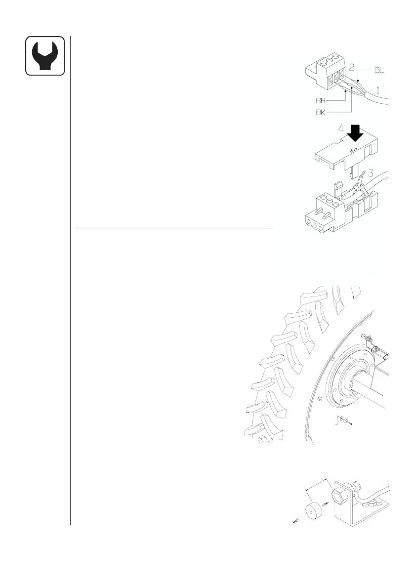
Transducer colour codes and plug assembly
1. Shorten cable to a suitable length.
2. Assemble as shown.
3. Run tie strap through hole under cable
grip and secure cable to plug housing.
4. Trim tie strap length and assemble the
housing. Tag the speed transducer by
folding the identification sticker around
the cable.
5. Secure plug housing with a tie strap.
HARDI transducers colour codes are as
follows. Includes speed, flow, area meter,
revolutions and pressure transducers.
Wire colour Code Connection for transducer
Brown BR 12 Volt supply
Black BK GND
Blue BL Signal
Speed transducer
Speed transducer is fitted as shown.
Hole size is 4.5 mm.
Magnets must be placed an equal
distance (and at least 150 mm) from one
another.
Recommended number of magnets
fitted are as follows:
Tractor front wheel
(rim size up to 20”) ........................ 4
Tractor rear wheel
(rim size over 20”) .........................6
Transmission drive-shaft ............... 1
The south side of the magnet must
face the transducer.
Distance between them must be 5 to 7 mm.
T165-0003
4.5 mm
3
/16
T165-0004
N
S
5-7 mm
1
/
8
-
1
/
4
 Loading...