2005 PDI: VRSC Models 6-3
INSTALLING MAXI-FUSE
NOTES
● The 40 amp Maxi-Fuse provides battery power to the
ignition switch and ECM. The Maxi-Fuse is not installed
at the factory. It is shipped in the fuse holder boot next to
the socket.
● It will also be necessary to install the fuel pump fuse that
is located in a spare fuse location. See Service Manual.
1. See Figure 6-1. Remove fastener at upper corner of lou-
vered cover and remove cover.
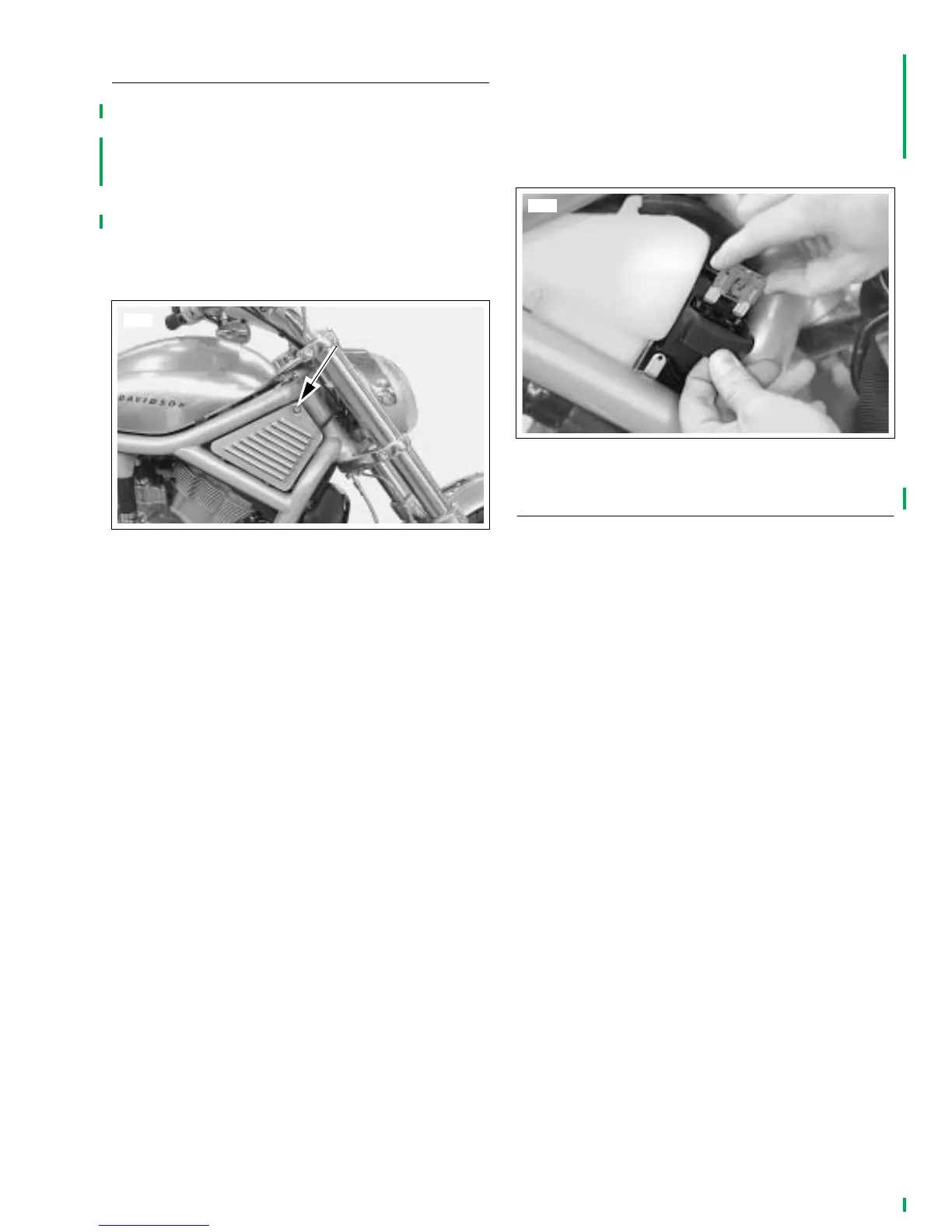
2. See Figure 6-2. The fuse holder and boot is located just
forward of the coolant reservoir. Fold back the flap on the
fuse holder boot and insert the fuse into the fuse holder
socket.
3. See Figure 6-1. Reinstall sidecover and secure with
screw. Tighten to 4.1-6.8 Nm (30-60 in-lbs).
SEATS AND PASSENGER STRAP
Refer to VRSC Models Owner’s Manual for seat and passen-
ger strap removal and installation instructions.
Figure 6-1. Removing Sidecover
9010
Figure 6-2. Inserting Maxi-Fuse